Magnetron control system, magnetron control method and high-frequency heating device

A control system and magnetron technology, applied in control/regulation systems, magnetrons, output power conversion devices, etc., can solve the problems of magnetron drive power module wiring and cost increase, and reduce the number of connections. To, reduce wiring and components, realize the effect of variable output

Active Publication Date: 2020-06-05
GUANGDONG MIDEA KITCHEN APPLIANCES MFG CO LTD +1
View PDF6 Cites 0 Cited by
  • Summary
  • Abstract
  • Description
  • Claims
  • Application Information

AI Technical Summary

Problems solved by technology

However, the related art has a problem in that the wiring of the magnetron drive power supply module is many, resulting in an increase in cost.

Method used


Image

  • Magnetron control system, magnetron control method and high-frequency heating device
  • Magnetron control system, magnetron control method and high-frequency heating device
  • Magnetron control system, magnetron control method and high-frequency heating device

Examples


Embodiment 1

[0053] When the status information of the power control unit 20 includes the switching times of the power control unit 20, it can be understood that when the control command received by the operation unit 30 continues to be at a high level, that is, the time for which the power control unit 20 is continuously turned on is longer than the preset time At T1, the processing circuit 54 calculates the high level, that is, the number of times the control instruction received by the operation unit 30 has changed from a high level to a low level before the power control unit 20 has been turned on longer than the preset time T1, that is, the power control unit 20 switching times, when the control command received by the operation unit 30 before the high level starts to change from high level to low level, that is, when the switching times of the power supply control unit 20 is 0, the processing circuit 54 will switch The on-off time ratio of the device 520 is controlled so that the volt...

Embodiment 2

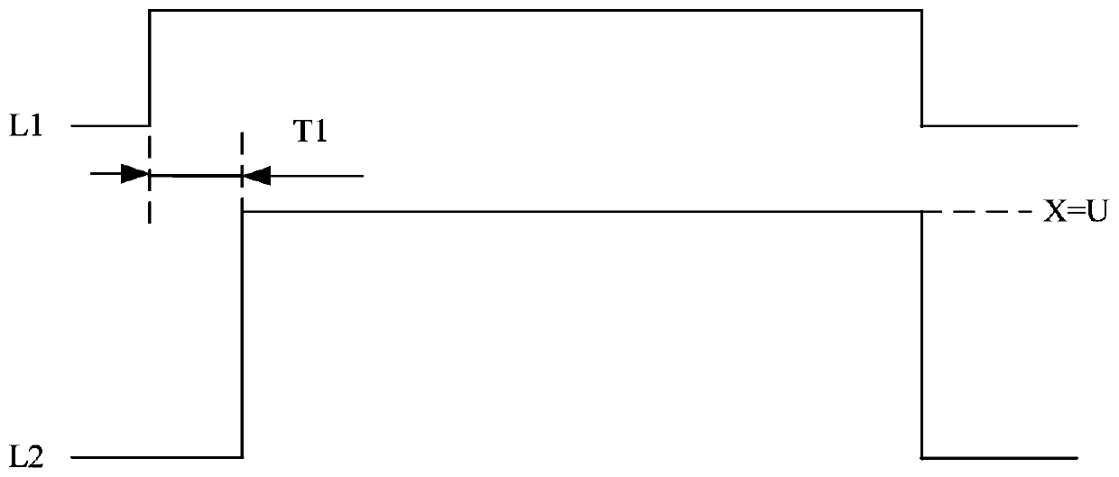
[0061] When the status information of the power control unit 20 includes the turn-on time of the power control unit 20, it can be understood that, as Figure 9 As shown, wherein, L1 represents the waveform diagram of the control command received by the operation unit 30, L2 represents the waveform diagram of the voltage applied to the magnetron 40 by the drive power supply module 50, and the voltage applied to the magnetron 40 by the drive power supply module 50 In the case of the maximum voltage U, the processing circuit 54 calculates the time T2 during which the control command received by the operation unit 30 is continuously at a high level, that is, the power control unit 20 is continuously turned on. If the time value is equal to the first preset value A, that is, T2 =A, then the processing circuit 54 controls the on-off time ratio of the switching device 520, so that the voltage X applied to the magnetron 40 by the drive power supply module 50 is set to 50% U, that is, X...


PUM


Abstract

The invention provides a magnetron control system, a magnetron control method and a high-frequency heating device, and the system comprises an AC input end which is used for receiving an AC power supply; a power supply control part used for controlling the alternating current input end to supply or stop supplying the alternating current power supply; an operation part connected with the power supply control part, wherein the operation part is used for receiving the control instruction and controlling the power supply control part to be turned on or turned off according to the control instruction; a driving power module, wherein the driving power supply module is connected with the alternating current input end through the power supply control part, is also connected with the magnetron, and is used for acquiring the state information of the power supply control part and converting the alternating current power supply according to the state information of the power supply control part in a preset time period, so that the voltage applied to the magnetron by the driving power supply module is adjusted. Thus, wiring and components connected to the driving power supply module can be reduced, the cost is reduced, and variable output of the driving power supply module can be realized.

Description

technical field [0001] The invention relates to the technical field of household electrical appliances, in particular to a magnetron control system, a high-frequency heating device, a method for the magnetron control system and a computer-readable storage medium. Background technique [0002] In the related art, it is usually necessary to connect the operation part to control the supply of AC power to the voltage supply wire of the drive power module and the output control signal line of the operation part to output the control signal to the drive power module for two-wire wiring, so as to realize the high-frequency heating device. The output is variable. However, there is a problem in the related art that the magnetron driving power supply module has many wirings, which leads to an increase in cost. Contents of the invention [0003] The present invention aims to solve one of the technical problems in the related art at least to a certain extent. [0004] Therefore, the...

Claims


Application Information

Patent Timeline
Patent Type & Authority Applications(China)
IPC IPC(8): H01J23/34H01J25/50H02M3/335H02M7/04
CPCH01J23/34H01J25/50H02M7/04H02M3/33523Y02B40/00
Inventor 高茂丰
Owner GUANGDONG MIDEA KITCHEN APPLIANCES MFG CO LTD
Why Eureka
Try Eureka