Correction mechanism and correction method on silicon wafer etching equipment

A technology for etching equipment and silicon wafers, which is applied in the manufacture of conveyor objects, electrical components, semiconductors/solid-state devices, etc., can solve the problems that the front and rear positions of silicon wafers cannot be corrected, and achieve the effect of reducing wear damage

Pending Publication Date: 2020-06-05
SUZHOU SAISEN ELECTRONICS TECH
View PDF0 Cites 8 Cited by
  • Summary
  • Abstract
  • Description
  • Claims
  • Application Information

AI Technical Summary

Problems solved by technology

[0004] One of the purposes of the present invention is to solve the problem that neither the fixed correction nor the dynamic correction in the prior art can correct the front and rear positions of the silicon wafer

Method used


Image

  • Correction mechanism and correction method on silicon wafer etching equipment
  • Correction mechanism and correction method on silicon wafer etching equipment
  • Correction mechanism and correction method on silicon wafer etching equipment

Examples


Embodiment 1

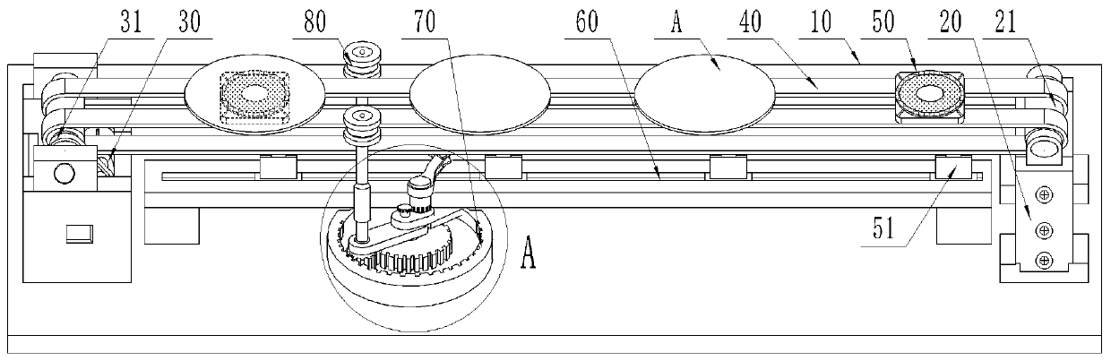
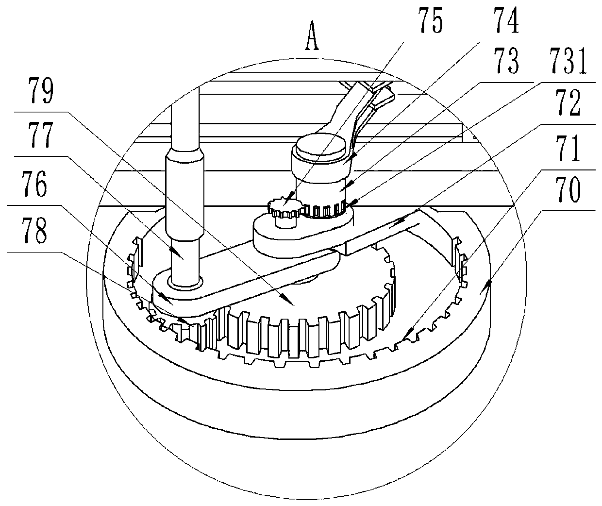
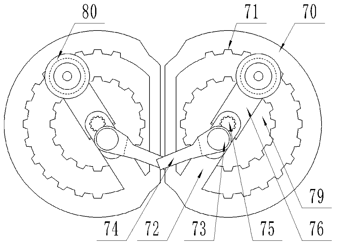
[0066] A correction mechanism on silicon wafer etching equipment, wherein, such as figure 1 As shown, it includes: a base 10 , a support seat 20 , a conveying roller 21 , a driving device 30 , a conveying belt 40 , a slide table 50 , a sliding seat 60 , a correction mechanism 70 , and a guide wheel 80 .

[0067] Two support bases 20 form a group, which are arranged opposite to each other. There is a gap between the support bases 20 . Each set of support bases 20 is installed on the left and right sides of the base 10 . The conveying rollers 21 are rotatably mounted on the support bases 20, and are installed on each set of support bases 20 respectively.

[0068] The driving device 30 is installed on the support base 20 , and the driving device 30 is power-connected to the conveying roller 21 . There are at least two conveyor belts 40 , and the conveyor belts 40 are arranged on the conveyor rollers 21 at intervals along the front and rear directions.

[0069] The slide table ...


PUM


Abstract

The invention discloses a correction mechanism on silicon wafer etching equipment, and relates to the technical field of silicon wafer production equipment. The correction mechanism comprises a base,a supporting seat, a conveying roller, a driving device, a conveying belt, a slide holder, a sliding seat, a correction mechanism and a guide wheel. The passive part of the correction mechanism is pushed by the trigger plate of the slide holder; a first gear with the diameter smaller than that of a rotating column is driven to rotate under transmission teeth on the rotating column (according to the transmission ratio principle in a mechanical transmission system, the rotating angle of the first gear equivalent to a small gear is larger than that of the rotating column equivalent to a large gear); the guide wheel is driven by the rotating part connected with the first gear to move in the arc direction from front to back along the arc end face of the silicon wafer, and front-back and left-right position correction of the silicon wafer is achieved. Besides, a second gear rotates along connecting teeth under the rotation of the rotating part, so that the guide wheel is driven to rotate. The static friction between the guide wheel and the silicon wafer is changed into dynamic friction, and the abrasion damage of the guide wheel to the silicon wafer is greatly reduced.

Description

technical field [0001] The invention relates to the technical field of silicon wafer production equipment, in particular to a correction mechanism on silicon wafer etching equipment. Background technique [0002] As the photovoltaic industry has attracted more and more attention, the production equipment of solar cells has also developed rapidly. [0003] At present, silicon wafer transmission and correction mechanisms are generally used in equipment such as solar wafer loading and unloading machines, loading machines, etching equipment, and silicon wafer transmission devices. There are two types of existing silicon wafer transmission and correction mechanisms. It is a fixed correction mechanism, which fixes wedge-shaped guide strips on both sides of the silicon wafer transmission line to guide the silicon wafer transmission. The other is a dynamic correction mechanism, that is, the cylinder controls the guide bar to push the silicon wafer to correct the position of the sil...

Claims


Application Information

Patent Timeline
Patent Type & Authority Applications(China)
IPC IPC(8): H01L21/677H01L21/68B65G47/24
CPCB65G47/24H01L21/67706H01L21/68
Inventor 伍志军
Owner SUZHOU SAISEN ELECTRONICS TECH
Why Eureka
Try Eureka