
Low-cost simple intelligent antenna device

A smart antenna and low-cost technology, applied in the field of antennas, can solve the problems of weak wireless coverage performance, high spatial correlation of MIMO channels, and large number of antennas, so as to improve wireless signal strength and wireless coverage capabilities, and improve MIMO multipath effect, overcoming the effect of frequent disconnection

Pending Publication Date: 2020-06-05
SHENZHEN JIXIANG TENGDA TECH
View PDF0 Cites 1 Cited by
  • Summary
  • Abstract
  • Description
  • Claims
  • Application Information

AI Technical Summary

Problems solved by technology

[0004] 1. Using the antenna layout scheme with the same number of MIMO streams, the same antenna polarization direction, and a fixed position, there will be multipath effects in some directions, which will cause wireless signal fading, lower wireless signal strength, and weaker wireless coverage performance. question;
[0005] 2. Adopt the antenna layout scheme with the same number of MIMO streams, the same antenna polarization direction, and a fixed position. There will be large spatial correlation of MIMO channels in some directions, high wireless communication bit error rate, and low wireless channel capacity. Directional issues with poor wireless performance;
[0006] 3. The current smart antennas all use directional antennas, and the number of antennas is more than 6. The switching selection of smart antennas is judged according to the user's location. However, in multi-user use, the antennas will switch frequently, which will easily cause users to drop the line, and the effect is not good. problem, and there are too many antennas, a special antenna control unit is required, and the cost is high

Method used

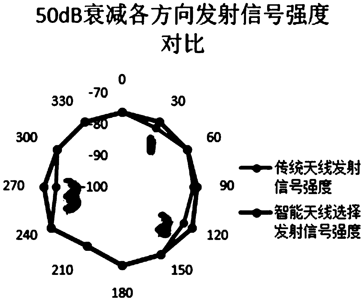
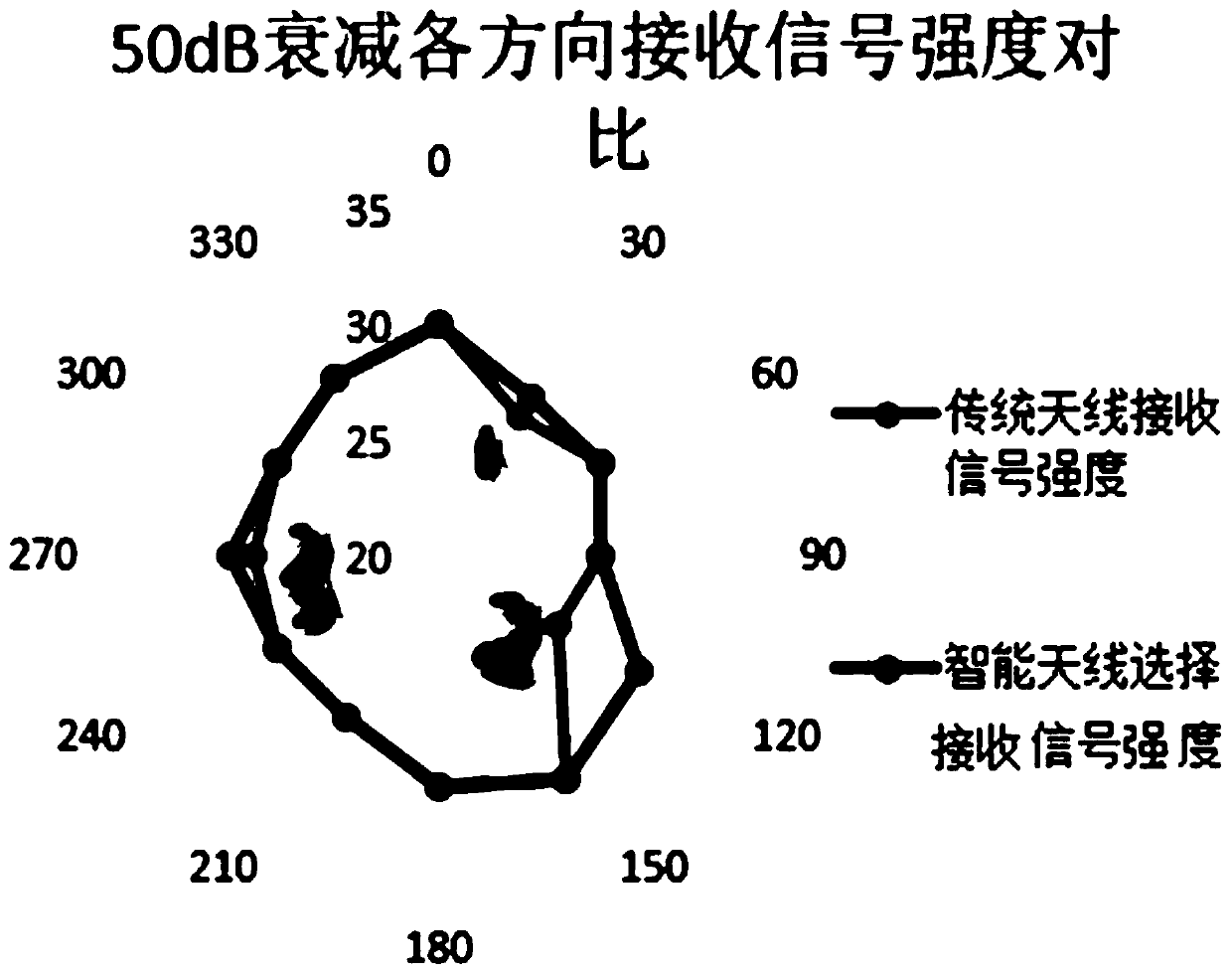

Image

  • Low-cost simple intelligent antenna device
  • Low-cost simple intelligent antenna device
  • Low-cost simple intelligent antenna device

Examples


Embodiment Construction

[0019] The present invention will be further described below in conjunction with the description of the drawings and specific embodiments.

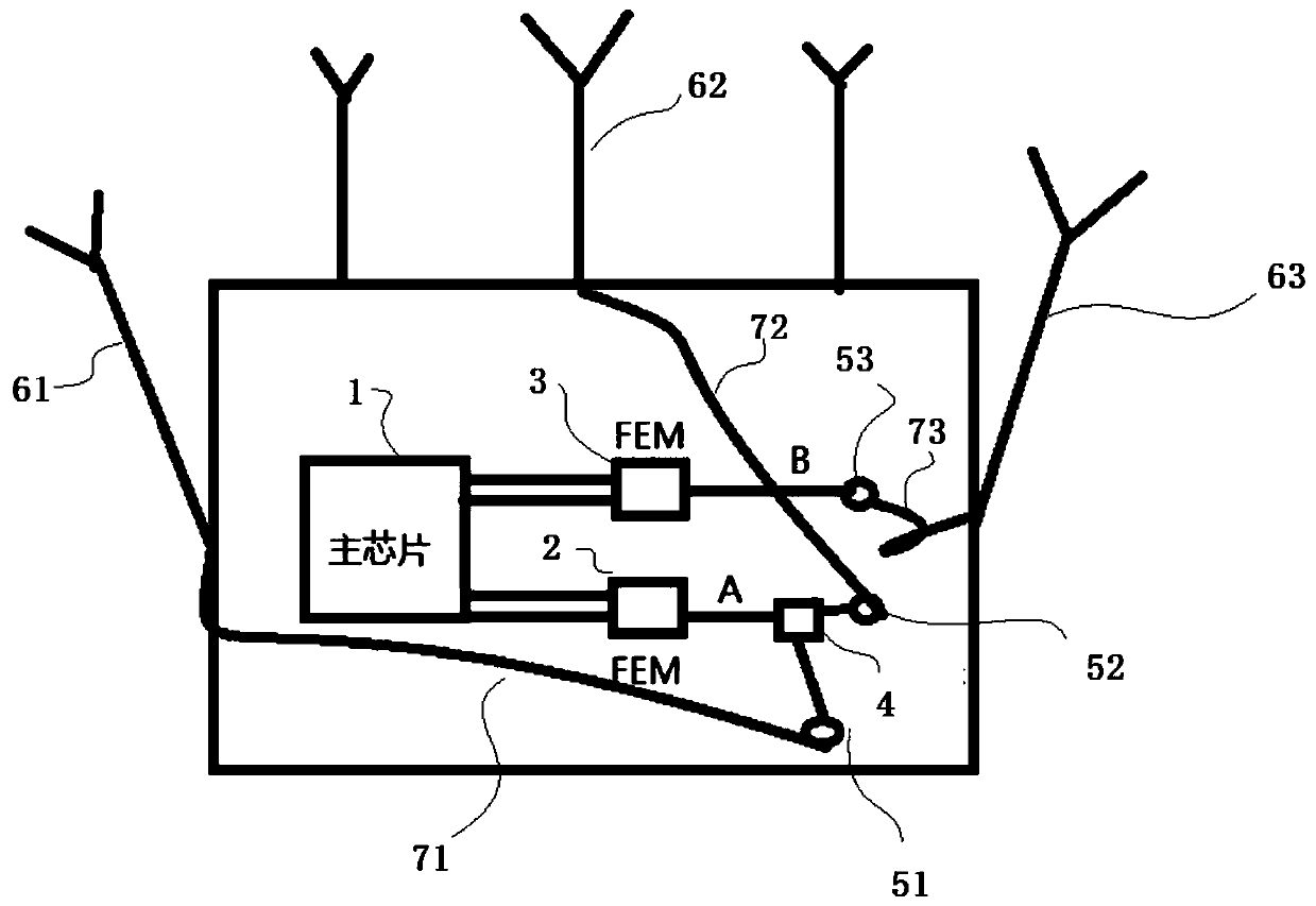
[0020] like figure 1 As shown, a low-cost simple smart antenna device (smart antenna for short), including a main chip 1, a first FEM radio frequency device 2, a second FEM radio frequency device 3, a radio frequency switch 4, a first antenna 61, a second antenna 62 and The third antenna 63, the wireless signal output end of the main chip 1 is connected to the first FEM radio frequency device 2 and the second FEM radio frequency device 3 respectively, and the output end of the first FEM radio frequency device 2 is connected to the radio frequency switch 4 connection, the output terminal of the first FEM radio frequency device 2 is connected to the first antenna 61 or the second antenna 62 through the radio frequency switch 4, and the first FEM radio frequency device 2 is connected by switching the radio frequency switch 4 The output end ...


PUM


Abstract

The invention provides a low-cost simple intelligent antenna device. The device comprises a main chip, a first FEM radio frequency device, a second FEM radio frequency device, a radio frequency switch, a first antenna, a second antenna and a third antenna. The wireless signal output end of the main chip is connected with the first FEM radio frequency device and the second FEM radio frequency device. The output end of the first FEM radio frequency device is connected with the radio frequency switch. The output end of the first FEM radio frequency device is connected with the first antenna or the second antenna through the radio frequency switch. The output end of the first FEM radio frequency device is connected with the first antenna or the second antenna by switching the radio frequency switch, and the output end of the second FEM radio frequency device is connected with the third antenna. The beneficial effects of the low-cost simple intelligent antenna device are that the cost is reduced, the MIMO multipath effect is improved, the wireless signal intensity and wireless coverage capability are improved, the directivity of the wireless performance of a whole machine is enhanced, and the problem of frequent disconnection is overcome.

Description

technical field [0001] The invention relates to antennas, in particular to a low-cost and simple smart antenna device. Background technique [0002] At present, most of the existing WIFI wireless network devices that support 802.11b / g / a / n / ac / ax network standards adopt an antenna layout scheme with the same number of MIMO streams, the same polarization direction, and fixed positions. [0003] But there are following defects: [0004] 1. Using the antenna layout scheme with the same number of MIMO streams, the same antenna polarization direction, and a fixed position, there will be multipath effects in some directions, which will cause wireless signal fading, lower wireless signal strength, and weaker wireless coverage performance. question; [0005] 2. Adopt the antenna layout scheme with the same number of MIMO streams, the same antenna polarization direction, and a fixed position. There will be a large spatial correlation of MIMO channels in some directions, high wireless...

Claims


Application Information

Patent Timeline
Patent Type & Authority Applications(China)
IPC IPC(8): H04B7/0413H01Q1/50H01Q21/00
CPCH04B7/0413H01Q1/50H01Q21/00
Inventor 魏红剑
Owner SHENZHEN JIXIANG TENGDA TECH
Learn More