Electricity storage device

A technology of power storage device and power storage element, which is applied to circuits, electrical components, secondary batteries, etc., can solve problems such as easy volatilization, and achieve the effect of preventing or suppressing ignition and preventing the chain of overheating states.

Pending Publication Date: 2020-06-05
GS YUASA INT LTD
View PDF3 Cites 3 Cited by
  • Summary
  • Abstract
  • Description
  • Claims
  • Application Information

AI Technical Summary

Problems solved by technology

The above non-aqueous solvents are usually volatile and flammable

Method used


Image

  • Electricity storage device
  • Electricity storage device
  • Electricity storage device

Examples


no. 1 approach

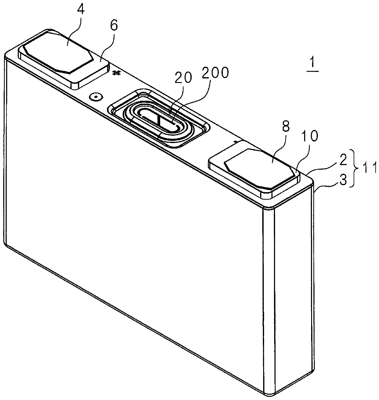
[0042] figure 1 It is a perspective view of the electricity storage element 1 . Although the case where the electricity storage element 1 is a lithium ion secondary battery is described below, the electricity storage element 1 is not limited to the lithium ion secondary battery.

[0043] The storage device 1 has a case 11 having a cover plate 2 and a case body 3, a positive terminal 4, a negative terminal 8, gaskets 6, 10, a burst valve 20, a current collector, and an electrode body (not shown).

[0044] The case 11 is formed of, for example, metal such as aluminum, aluminum alloy, or stainless steel, or synthetic resin, and is formed in a rectangular parallelepiped shape, and accommodates an electrode body and an electrolytic solution (not shown). Alternatively, the casing may also be a soft casing using laminated sheets.

[0045] The positive terminal 4 has a shaft portion penetrating through the cover plate 2 and a plate portion provided at one end of the shaft portion. ...

no. 2 approach

[0119] Figure 7 It is a perspective view of the cooling module 35 of the second embodiment. In the picture with image 3 The same symbols are used for the same parts, and detailed descriptions are omitted.

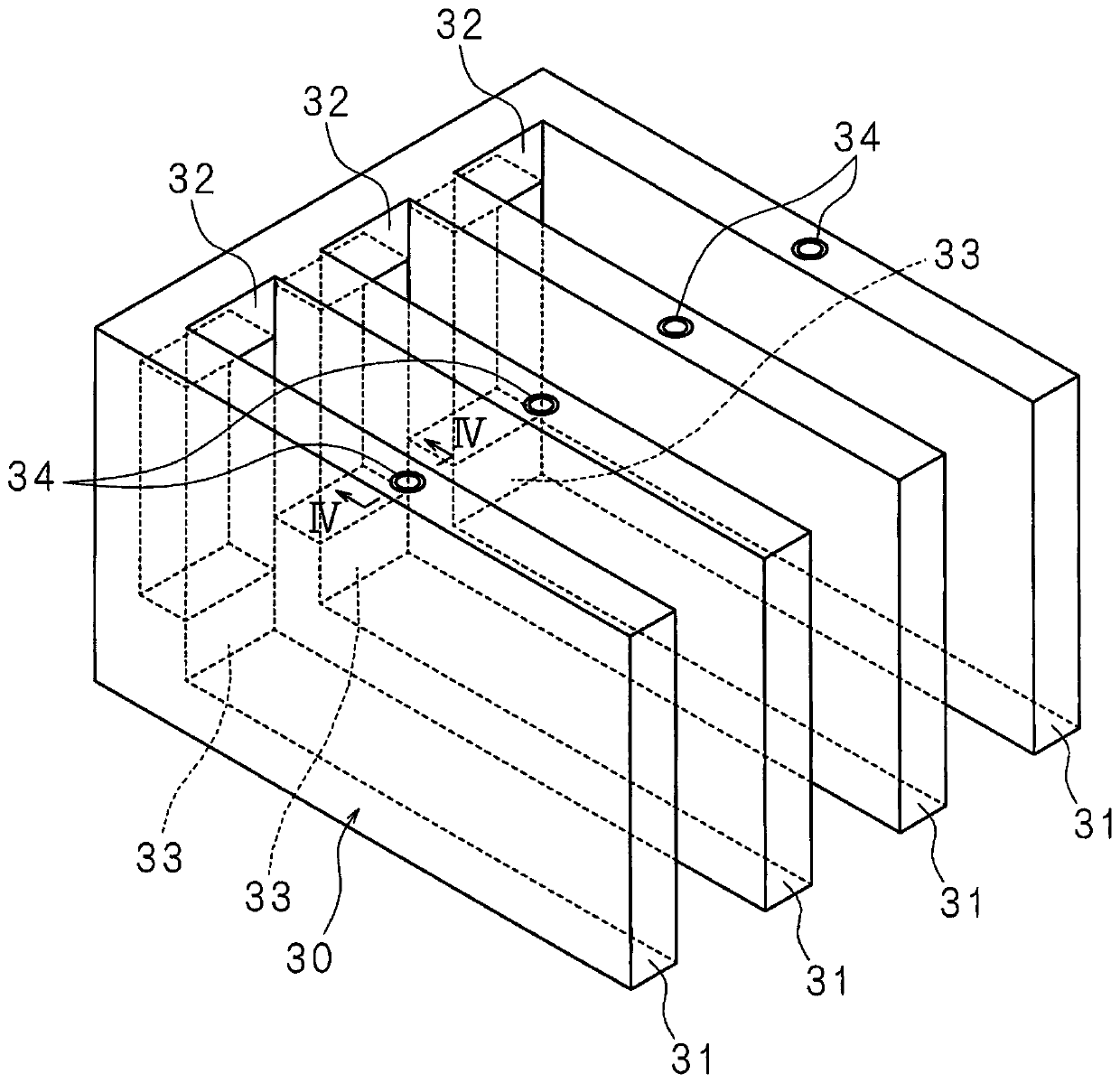
[0120] The cooling module 35 has four cooling sections 31 and cooling plates 36 .

[0121] The cooling module 35 is different from the first embodiment in which the four cooling units 31 are connected by the connection parts 32 and 33 , in that the end surfaces 31 a of the four cooling units 31 are in contact with the cooling plate 36 . The flame retardant L is accommodated in the cooling unit 31 in the same manner as in the first embodiment.

[0122] The internal spaces of the cooling unit 31 and the cooling plate 36 may or may not communicate with each other.

[0123] Figure 8 It is explanatory drawing of the case where internal spaces are connected in this embodiment. The power storage element 1 is inserted between the cooling parts 31 , and the flame retardant ...

no. 4 approach

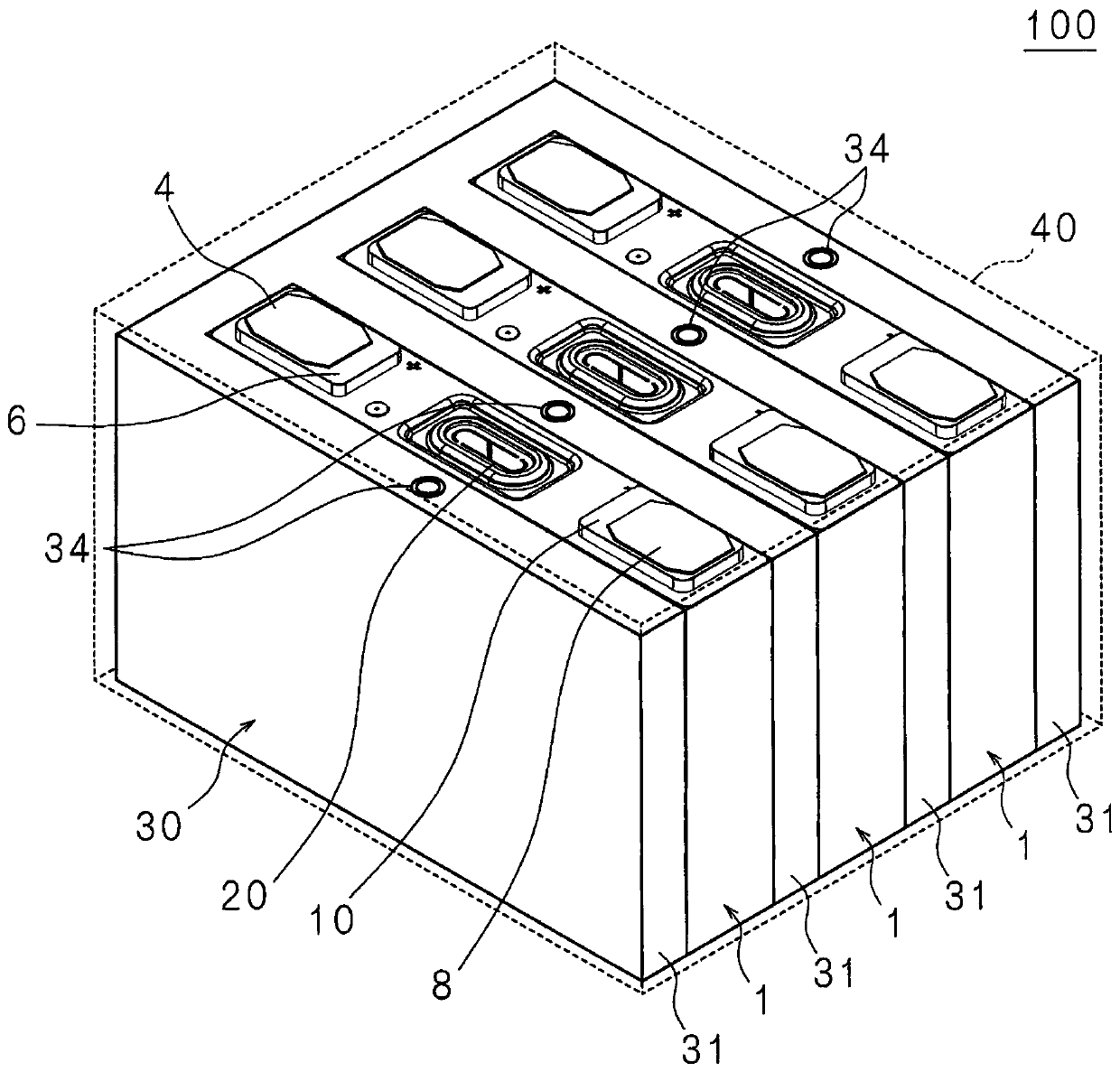
[0142] Figure 11 It is a perspective view of the power storage device 101 of the fourth embodiment. In the picture with figure 2 The same symbols are used for the same parts, and detailed descriptions are omitted.

[0143] Power storage device 101 is different from power storage device 100 according to the first embodiment in that it does not have connection parts 32 and 33 for connecting cooling part 31 . Cooling unit 31 is independently disposed between power storage elements 1 or between power storage elements 1 and the inner surface of case 40 . A flame retardant L (not shown) is accommodated in the cooling unit 31 .

[0144] When the energy storage element 1 generates heat, the flame retardant L in the cooling portion 31 in contact with the energy storage element 1 evaporates by taking away the heat of vaporization from the energy storage element 1 , and rapidly cools the energy storage element 1 . The generated gas is convected, cooled by the outside of power stora...


PUM


Abstract

The invention provides an electricity storage device. The electricity storage device (100) is provided with a plurality of electricity storage elements (1) and a cooling module (30) which cools the electricity storage elements (1). The cooling module (30) comprises at least a cooling unit (31) which is arranged between the electricity storage elements (1) and internally contains a flameproofing agent, thereby cooling the electricity storage elements (1) by means of heat absorption during vaporization of the flameproofing agent. Consequently, the electricity storage elements (1), in which heathas been generated, are successfully cooled by the cooling unit (31) that is in contact with the electricity storage elements (1) by means of the vaporization heat at the time when the flameproofing agent contained within the cooling unit is vaporized, thereby preventing a chain of overheated states among the electricity storage elements (1).

Description

technical field [0001] The present invention relates to an electrical storage device having a plurality of electrical storage elements. Background technique [0002] Energy storage elements that can be charged and discharged are used in various devices such as mobile phones and automobiles. Among them, electric vehicles (EVs) and plug-in hybrid electric vehicles (PHEVs), which use electric energy as a power source, require a large amount of energy. Therefore, a large-capacity power storage device having a plurality of power storage elements is mounted. [0003] In such an electric storage device, when the temperature of any one of the electric storage elements rises excessively due to some reason other than normal use, the heat from the electric storage element spreads to the adjacent electric storage elements. Conduction heats up the adjacent storage elements. Thus, when the temperature of the active material of the electrode of the adjacent energy storage element rises a...

Claims


Application Information

Patent Timeline
Patent Type & Authority Applications(China)
IPC IPC(8): H01M10/613A62C3/06H01M2/10H01M10/625H01M10/647H01M10/653H01M10/6552H01M10/6557H01M10/6569H01M50/209H01M50/289
CPCH01M10/613H01M10/625H01M10/647H01M10/653H01M10/6557H01M10/6569A62C3/06Y02E60/10H01M50/209H01M50/289
Inventor 稻益德雄向井宽奥山良一
Owner GS YUASA INT LTD
Why Eureka
Try Eureka