
Automatic vacuum cup spraying device

A technology for automatic spraying and thermos cups, applied in spraying devices, liquid spraying devices, etc., can solve the problems of low work efficiency, large floor space, and large size of spraying devices, so as to reduce labor intensity, reduce floor space, The effect of improving work efficiency

Pending Publication Date: 2020-06-09
方永东
View PDF0 Cites 4 Cited by
  • Summary
  • Abstract
  • Description
  • Claims
  • Application Information

AI Technical Summary

Problems solved by technology

[0002] As a daily necessities, stainless steel thermos cups need to be sprayed on the inner and outer surfaces of the thermos cups during the production process; the spraying equipment of the thermos cups mainly includes four parts: feeding, spraying, drying and unloading, four of which are The thermos cups are transported through the tank chain reciprocating structure, which makes the whole spraying device larger in size and larger in floor area; and the existing thermos cup spraying equipment can only spray one surface of the thermos cup first, Wait for the sprayed surface to dry before spraying another surface, resulting in lower overall work efficiency
Therefore, the existing spraying equipment for the production of thermos cups has the problems of large footprint and low work efficiency.

Method used


Image

  • Automatic vacuum cup spraying device
  • Automatic vacuum cup spraying device
  • Automatic vacuum cup spraying device

Examples


Embodiment Construction

[0018] The present invention will be further described below in conjunction with the accompanying drawings and embodiments, but not as a basis for limiting the present invention.

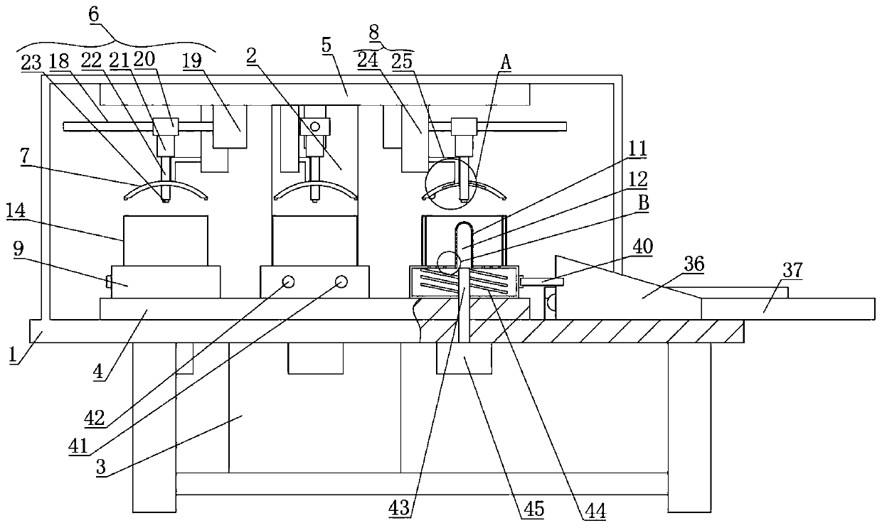
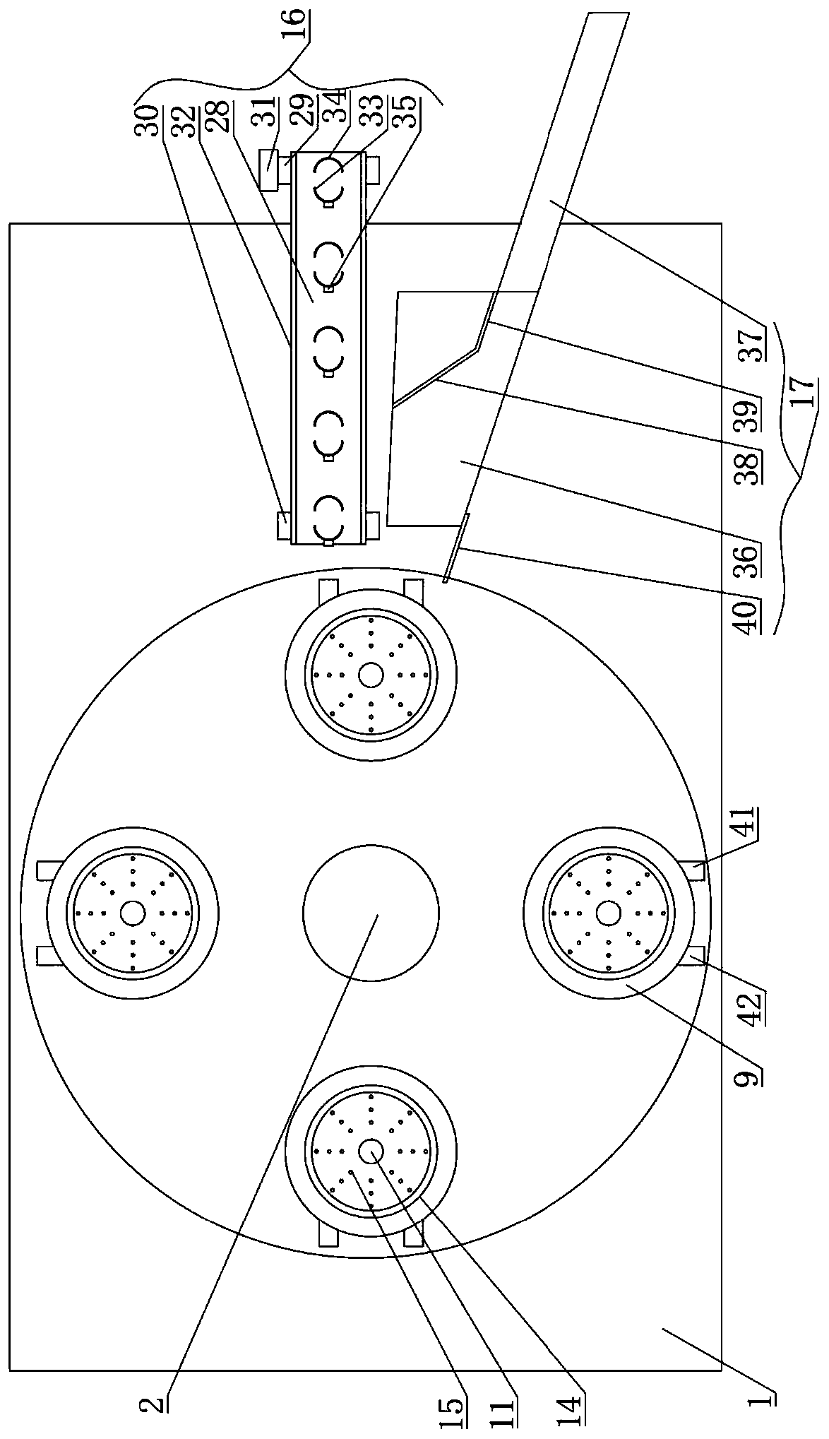
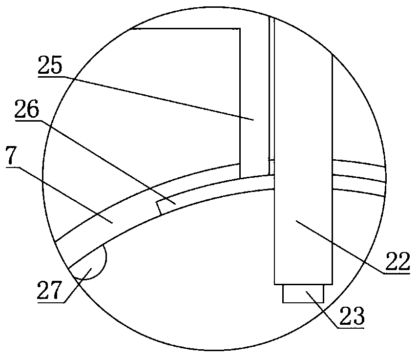
[0019] Example. A thermos cup automatic spraying device, constituted as Figures 1 to 4 As shown, including the installation frame 1, the installation frame 1 is provided with a drive rod 2; the bottom end of the drive rod 2 is equipped with a torque motor 3, and the drive rod 2 is fixedly installed with a lower turntable 4 located on the inner bottom surface of the installation frame 1; The top of the lower turntable 4 is provided with an upper turntable 5 positioned on the inner top surface of the installation frame 1, and the upper turntable 5 and the lower turntable 4 are arranged concentrically; Each moving device 6 is connected with a sealing cover 7; one side of each moving device 6 is connected with a negative pressure device 8, and the negative pressure device 8 is connected with the seali...


PUM


Abstract

The invention discloses an automatic vacuum cup spraying device which comprises a mounting frame, wherein a driving rod is arranged on the mounting frame; a torque motor, a lower rotary disc and an upper rotary disc are mounted on the driving rod; a plurality of movable devices are arranged on the upper rotary disc; a sealing cap and a negative pressure device are connected onto each of the movable devices; a coating seat is arranged on the lower rotary disc; a storing cavity, a support rod and a flowing cavity are formed in the coating seat; a plurality of outflow holes are formed in the flowing cavity; a fixed annular plate is arranged on the coating seat; a plurality of discharging holes are formed between the fixed annular plate and the support rod; and a feeding device and a discharging device are arranged on one side of the lower rotary disc. The automatic vacuum cup spraying device can improve the working efficiency and also has the advantages of being small in occupied area, simple in structure, low in labor intensity, excellent in coating effect, low in production cost, long in service life, convenient to use and high in coating utilization ratio and operating stability.

Description

technical field [0001] The invention relates to a thermos cup spraying device, in particular to an automatic thermos cup spraying device. Background technique [0002] As a daily necessities, stainless steel thermos cups need to be sprayed on the inner and outer surfaces of the thermos cups during the production process; the spraying equipment of the thermos cups mainly includes four parts: feeding, spraying, drying and unloading, four of which are The thermos cups are transported through the tank chain reciprocating structure, which makes the whole spraying device larger in size and larger in floor area; and the existing thermos cup spraying equipment can only spray one surface of the thermos cup first, Wait for the sprayed surface to dry before spraying another surface, resulting in lower overall work efficiency. Therefore, the existing spraying equipment for the production of thermos cups has the problems of large footprint and low work efficiency. Contents of the inve...

Claims


Application Information

Patent Timeline
Patent Type & Authority Applications(China)
IPC IPC(8): B05B13/02B05B15/25B05B13/06B05B12/08B05B9/03
CPCB05B9/03B05B12/081B05B13/0242B05B13/0609B05B13/069B05B15/25
Inventor 方永东
Owner 方永东
Learn More