
Rotor painting machine

A rotor and fuselage technology, applied in the field of rotor painting machines, can solve the problems of difficult quality assurance, affecting people's health, high labor intensity, etc., and achieve the effects of convenient debugging and maintenance, high efficiency and good effect

Inactive Publication Date: 2020-06-09
李树明
View PDF0 Cites 1 Cited by
  • Summary
  • Abstract
  • Description
  • Claims
  • Application Information

AI Technical Summary

Problems solved by technology

[0004] In the production of motors, most of the rotors are painted by hand, so the quality is difficult to guarantee, the paint is uneven, the work efficiency is low, and the labor intensity is high. Some use spraying, which wastes paint, and pollutes the environment and affects people's health.

Method used


Image

  • Rotor painting machine
  • Rotor painting machine
  • Rotor painting machine

Examples


Embodiment Construction

[0014] The invention is realized in the following ways:

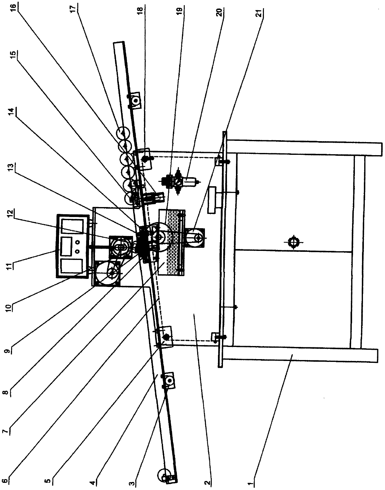
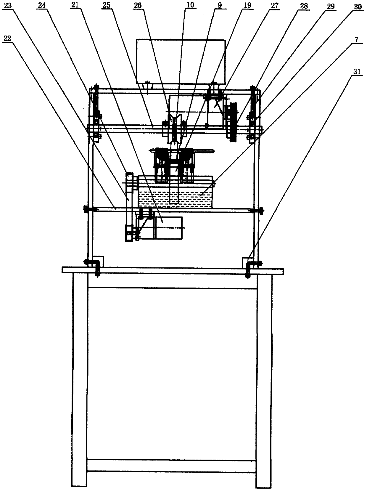
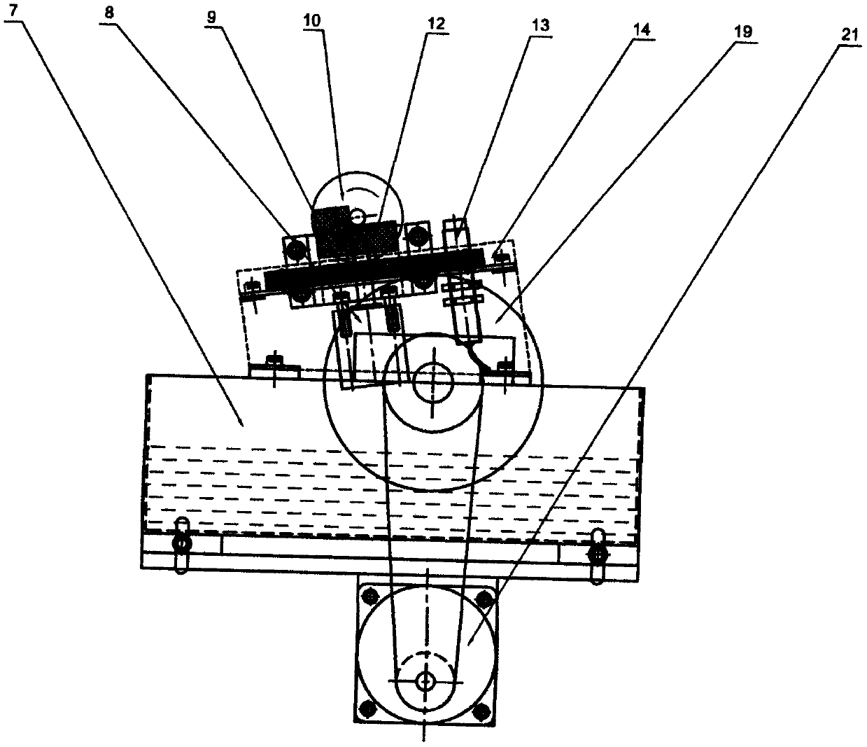
[0015] The invention uses the guide rail (4) and the cylinder to automatically load and unload, the rotor (10) is rolled into the oil cotton box (14), the motor drives the rotor (10), the paint wheel (19) is supplied, and the rotor rubs the oil cotton (9) to apply Painted, its characteristics: the machine (1) is equipped with a fuselage (2), the fuselage (2) is formed by connecting two plates, a connecting rod (18), and a connecting block (31). (2) A guide rail (4) is installed inside. The guide rail (4) is composed of: a support (3), a support (5), a blocking cylinder (8), a block (12), a blocking device (15), a blocking cylinder (16), the paint box part (7) and oil cotton box (14) are installed under the guide rail. The paint box part (7) is composed of: motor (21), support plate (22), belt (23), belt The wheel (24), the rotor drive wheel (26), the motor (29), the paint wheel (19), and the oil cotton box (14) are compos...


PUM


Abstract

The invention relates to a rotor painting machine. A guide rail air cylinder is adopted for automatic feeding and discharging; a roller rolls into an oil cotton box; a motor drives the rotor and a paint supply wheel, and the rotor rub oil cotton to be painted. The feeding part of the rotor painting machine is composed of a guide rail, a blocking air cylinder, the oil cotton, the rotor, an operation box, a stop dog, a sensor, a stopper and another blocking air cylinder; and the painting part of the rotor painting machine is composed of a paint box, the blocking air cylinder, the oil cotton, therotor, the oil cotton box, the paint supply wheel, a paint supply wheel motor, a support plate, a belt, a belt pulley, a driving wheel shaft, a rotor driving wheel, a driving wheel motor, another belt pulley, an adjusting screw, and a mounted bearing. The rotor painting machine automatically feeds and discharges and paints, paints uniformly and reliably, better than the manual painting effect, avoids paint splashing, spraying, pollution and waste, is high in efficiency, excellent in performance and convenient to debug and repair, and the specification size of the painting rotor can be adjusted.

Description

[0001] 1. Technical Field: [0002] This machine is an invention involving a new type of rotor automatic painting equipment. [0003] 2. Background technology: [0004] In the motor production, the rotor painting is mostly manually painted, so the quality is difficult to guarantee, the painting is uneven, the work efficiency is low, the labor intensity is high, and some use spraying, which wastes the paint, and pollutes the environment and also affects human health. [0005] 3. Summary of the invention: [0006] The invention adopts the guide rail (4) and the cylinder to automatically load and unload, the rotor (10) is rolled into the oil cotton box (14), the motor drives the rotor to supply the paint wheel (19), and the rotor rubs the oil cotton (9) to apply paint. [0007] The feeding part of the machine is composed of guide rail (4), blocking cylinder (8), oil wool (9), rotor (10), operation box (11), stop (12), sensor (13), stopper (15) ), which is composed of blocking cylinder (16)....

Claims


Application Information

Patent Timeline
Patent Type & Authority Applications(China)
IPC IPC(8): B05C1/02B05C13/02
CPCB05C1/02B05C13/02
Inventor 李树明
Owner 李树明
Learn More