

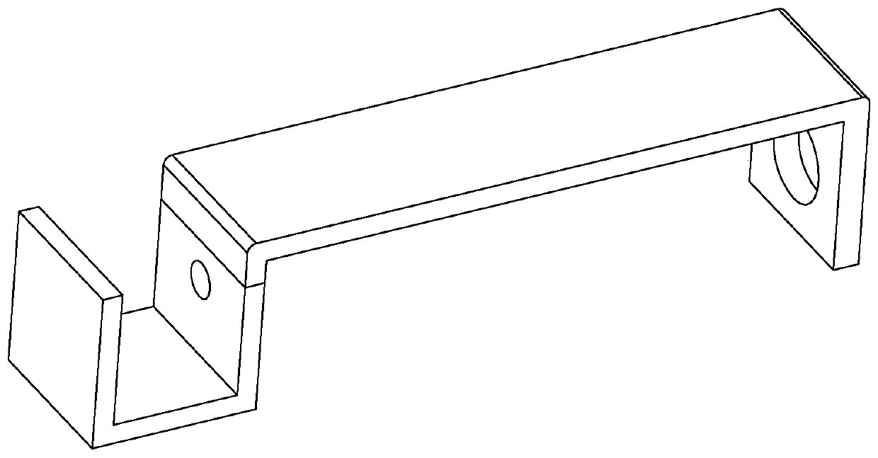
Curtain rod metal piece stamping stepping die
A technology of metal parts and curtain rods, which is applied in the field of metal stamping, can solve the problems of limited size of the upper and lower die components and affect the working efficiency of the equipment, and achieve the effects of saving space, improving work efficiency and high precision
- Summary
- Abstract
- Description
- Claims
- Application Information
AI Technical Summary
Problems solved by technology
Method used
Image

Examples
Embodiment Construction
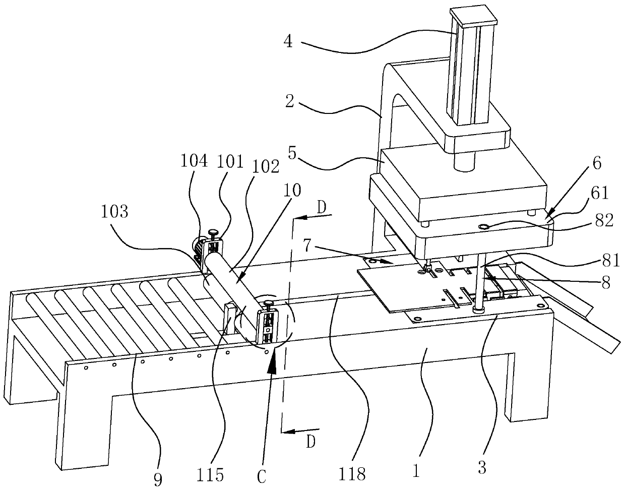
[0037] The present invention will be described in further detail below in conjunction with the accompanying drawings.
[0038] refer to figure 2 , is a stepping die for stamping curtain rod metal parts disclosed in the present invention, comprising a machine base 1, a cantilever 2 protruding upward from one side of the machine base 1, a base 3 arranged on the machine base 1, and a base 3 fixedly connected to the cantilever 2 The stamping cylinder 4 above, the upper mold base 5 connected to the bottom of the stamping cylinder 4, the upper mold assembly 6 located at the bottom of the upper mold base 5 and the lower mold assembly 7 located above the base 3, the piston rod of the stamping cylinder 4 Arranged vertically downward, the upper die base 5 is connected to the end of the piston rod of the stamping cylinder 4, and a punching passage is formed between the upper die assembly 6 and the lower die assembly 7, and the sheet material is conveyed through the punching passage. A ...
PUM
 Abstract
Description
Claims
Application Information