High-precision guide rail correction device

A correction device and high-precision technology, applied in metal processing machinery parts, maintenance and safety accessories, metal processing equipment, etc., can solve problems such as unbalanced force correction accuracy, reduce processing costs and processing difficulties, and improve calibration accuracy , the effect of reducing the impact

Active Publication Date: 2020-06-09
深圳市强华科技发展有限公司
View PDF7 Cites 2 Cited by
  • Summary
  • Abstract
  • Description
  • Claims
  • Application Information

AI Technical Summary

Problems solved by technology

[0005] The purpose of the present invention is to provide a high-precision guide rail correction device, through the cooperation of the correction block and the base, under the drive of the adjustment bolt, the simultaneous movement

Method used


Image

  • High-precision guide rail correction device
  • High-precision guide rail correction device
  • High-precision guide rail correction device

Examples


Embodiment Construction

[0034] The present invention will be described in further detail below in conjunction with the accompanying drawings.

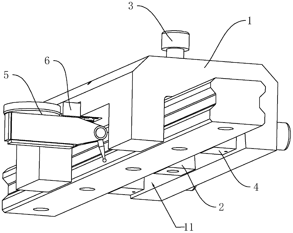
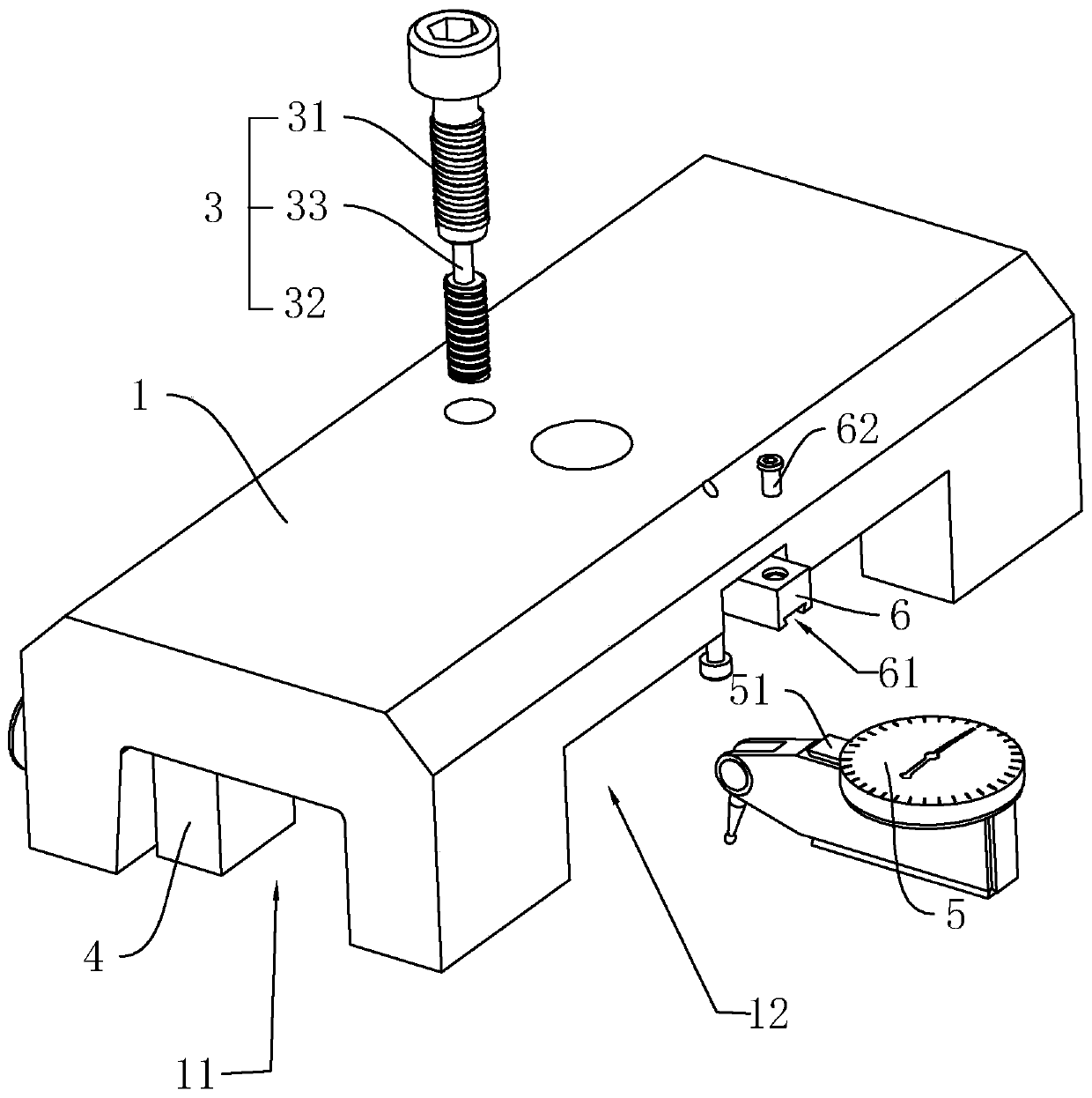
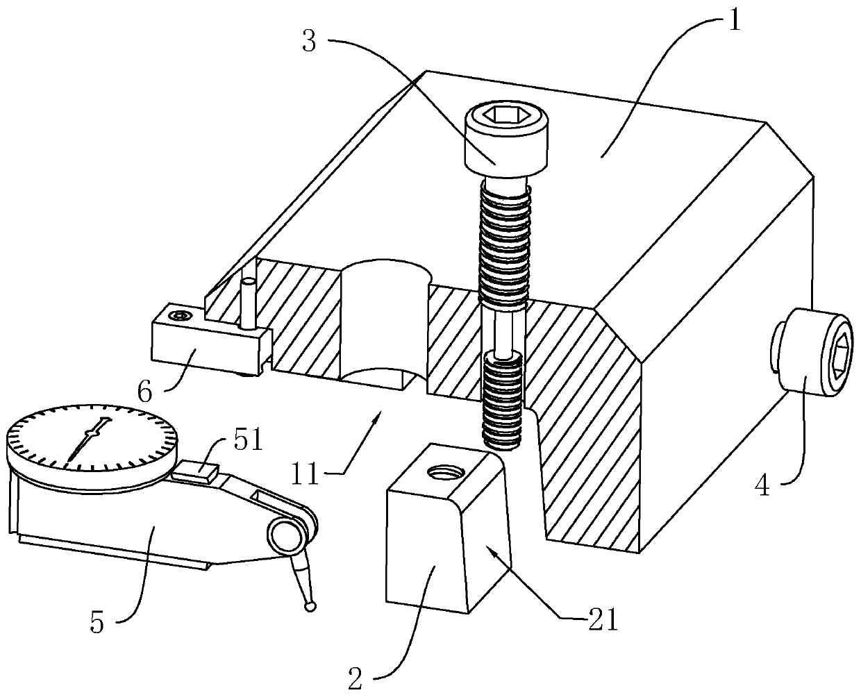
[0035] refer to figure 1 , is a high-precision guide rail correction device disclosed in the present invention, including a base 1, wherein the base 1 is provided with a correction groove 11 for accommodating and resisting the guide rail along its length direction, and the setting of the correction groove 11 makes the base 1 in an inverted U shape type setting. In order to facilitate the guide rail to enter the correction groove 11, the groove width of the correction groove 11 is larger than the width of the guide rail, and the inner wall of one side of the correction groove 11 is vertically slidably connected with the correction block 2, and the two sides of the correction block 2 are connected with the side wall of the guide rail and the correction groove respectively. 11 The side wall is in conflict. The side wall of the correction groove 11 away from the...


PUM

PropertyMeasurementUnit
Angleaaaaaaaaaa

Abstract

The invention relates to a high-precision guide rail correction device and belongs to the technical field of high-precision correction devices. The high-precision guide rail correction device comprises a base, wherein a correcting groove for accommodating and being propped against a guide rail is formed in the base in the length direction of the base in a penetrating manner; a correcting block isvertically arranged on the inner wall of one side of the correcting groove in a sliding manner; the two sides of the correcting block are propped against the side walls of the guide rail and the sidewalls of the correcting groove; the side wall, far away from one side of the correcting block, of the correcting groove is propped against the other side wall of the guide rail; an adjusting bolt is jointly connected between the correcting block and the base, vertically penetrates through the base, is in threaded connection with the base and drives the correcting block to vertically move up an down; and when the correcting block moves upwards, the correcting block moves towards one side of the guide rail. According to the high-precision guide rail correction device, through matching of the correcting block and the base, and under driving of the adjusting bolt, the correcting block simultaneously moves in the vertical and horizontal directions to replace the traditional manner that the guide rail is manually broken off, and the problem about correcting precision caused by unbalanced force application is solved.

Description

technical field [0001] The invention relates to the technical field of high-precision correction devices, in particular to a high-precision guide rail correction device. Background technique [0002] Drilling refers to the operation of machining holes on solid materials with a drill bit. Drilling machines are widely used in the field of mechanical processing. With the advancement of science and technology, CNC drilling machines and fully automatic drilling machines have gradually replaced manual drilling machines, not only drilling efficiency but also drilling progress have been greatly improved. [0003] Both the CNC drilling machine and the fully automatic drilling machine include a drilling device and a guide rail for the movement of the drilling device. The straightness of the guide rail directly affects the position of the drilling device on the guide rail, thereby affecting the drilling accuracy. The guide rail will be deformed and bent due to extrusion during use, wh...

Claims


Application Information

Patent Timeline
IPC IPC(8): B23Q11/00B23P6/00
CPCB23P6/00B23Q11/001
Inventor 黄永强陈舒海谢明刘树成陈小东
Owner 深圳市强华科技发展有限公司
Why Eureka
Try Eureka