Cam driving mechanism and offset printing machine with same
A driving mechanism and cam technology, applied in rotary printing machines, lithographic rotary printing machines, printing, etc., can solve problems such as socket wear, difficulty in disassembly, large gap between pins and sockets, etc., to ensure assembly stability and complete rotation Synchronization, convenient disassembly and assembly
- Summary
- Abstract
- Description
- Claims
- Application Information
AI Technical Summary
Problems solved by technology
Method used
Image

Examples
Embodiment 1
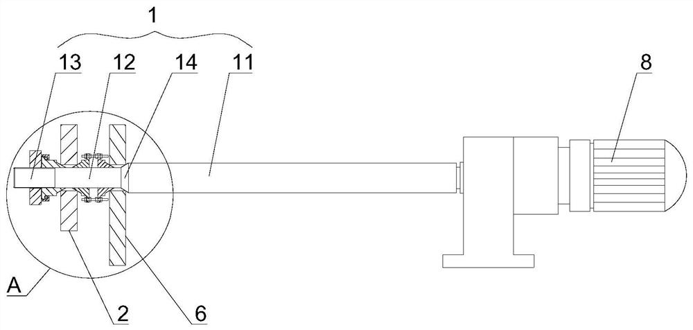
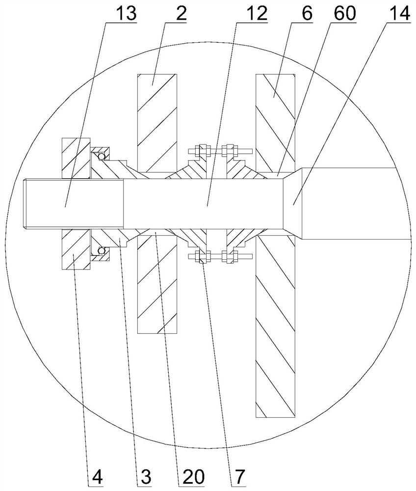
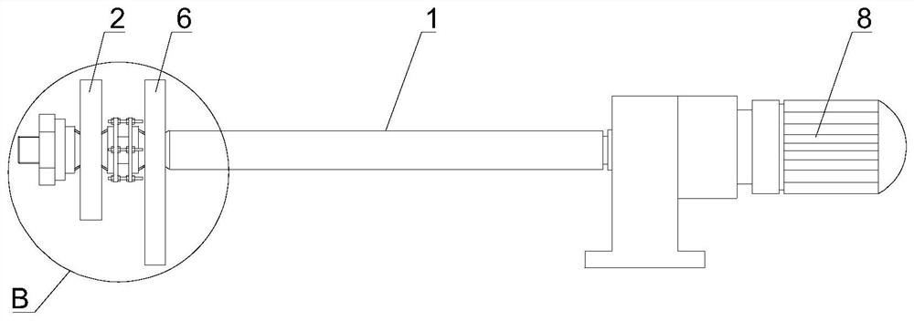
[0034] Such as Figure 1 to Figure 11 As shown, a cam driving mechanism provided in this embodiment includes a wheel shaft 1 , a first cam 2 , an expansion taper sleeve 3 , and a locking screw sleeve 4 . The axle 1 includes a main section 11, an assembly section 12, and a threaded section 13 arranged in sequence along the same axis. The assembly section 12 is located between the main section 11 and the threaded section 13, and the main section 11, the assembly section 12, and the threaded section 13 are integrated. The first cam 2 is provided with a first assembly through hole 20 that runs through the first cam 2. The first cam 2 is sleeved on the assembly section 12 through the first assembly through hole 20. The shape of the first assembly through hole 20 is the same as that of the assembly section. The shape of 12 is adapted to ensure the consistency and continuity of the gap formed between the first assembly through hole and the assembly section, so as to facilitate the un...
Embodiment 2
[0045] The difference between embodiment 2 and embodiment 1 is:
[0046] The cam drive mechanism also includes a second cam 6 and a double-headed expansion taper sleeve 7, the second cam 6 is provided with a second assembly through hole 60 passing through the second cam 6, and the second cam 6 is set through the second assembly through hole 60 Located on the assembly section 12 , the shape of the second assembly through hole 60 matches the shape of the assembly section 12 . The double-ended expansion taper sleeve 7 is sleeved on the assembly section 12, the double-ended expansion taper sleeve 7 is located between the first cam 2 and the second cam 6, and the double-ended expansion taper sleeve 7 gradually becomes smaller from the middle to both ends , and the end of the double-ended expansion taper sleeve 7 close to the first cam 2 extends into the gap formed between the first assembly through hole 20 and the assembly section 12, and the end of the double-head expansion taper ...
PUM
 Abstract
Description
Claims
Application Information
 - R&D
- Intellectual Property
- Life Sciences
- Materials
- Tech Scout
- Unparalleled Data Quality
- Higher Quality Content
- 60% Fewer Hallucinations
Browse by: Latest US Patents, China's latest patents, Technical Efficacy Thesaurus, Application Domain, Technology Topic, Popular Technical Reports.
© 2025 PatSnap. All rights reserved.Legal|Privacy policy|Modern Slavery Act Transparency Statement|Sitemap|About US| Contact US: help@patsnap.com