Brake system for new energy vehicle, and control strategy

A braking system and new energy vehicle technology, applied in the direction of braking safety systems, brakes, braking transmissions, etc., can solve problems such as braking failures

Active Publication Date: 2020-06-09
ZHEJIANG LEAPMOTOR TECH CO LTD
View PDF11 Cites 5 Cited by
  • Summary
  • Abstract
  • Description
  • Claims
  • Application Information

AI Technical Summary

Problems solved by technology

[0003] In view of the problem in the prior art that new energy vehicles rely solely on vacuum pumps to obtain brake boosting, vacuum pump failures are prone to cause braking failures. This invention designs a braking system and control strategy for new energy vehicles. When the vacuum boosting system fails At this time, the brake in

Method used


Image

  • Brake system for new energy vehicle, and control strategy
  • Brake system for new energy vehicle, and control strategy
  • Brake system for new energy vehicle, and control strategy

Examples


Embodiment

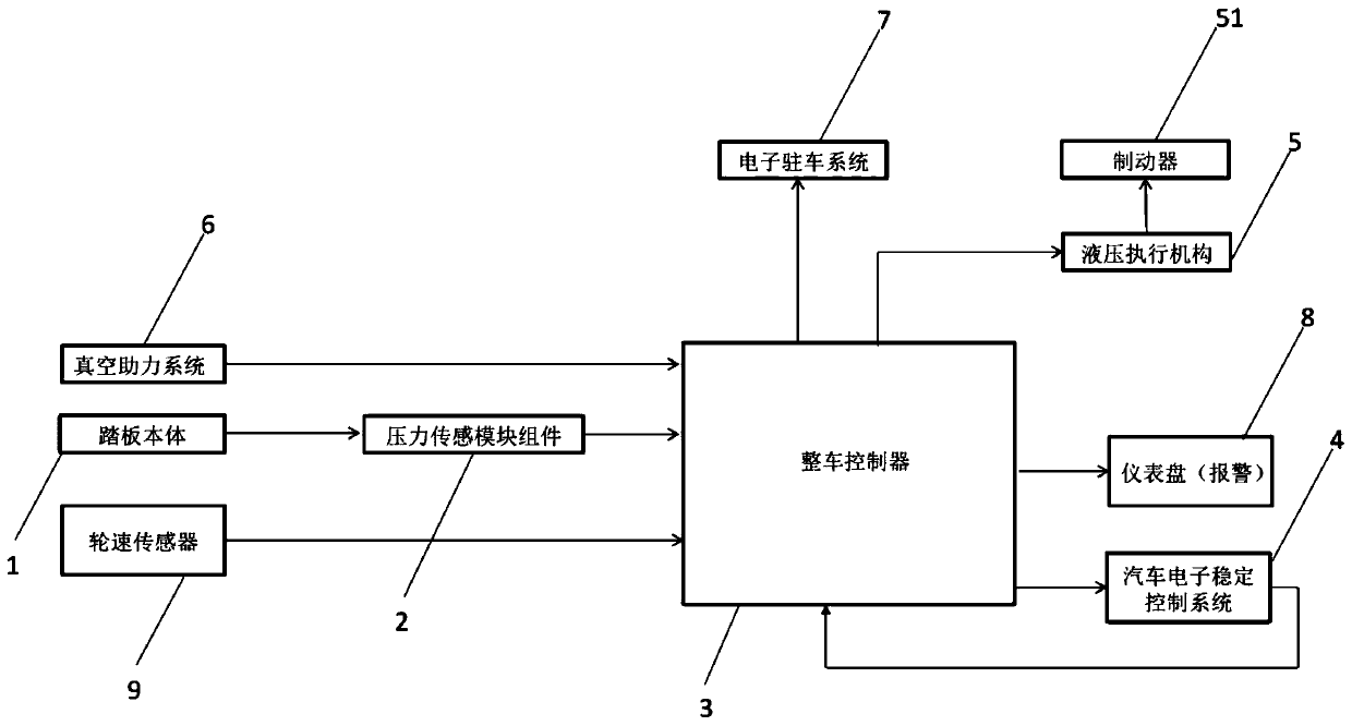
[0033] Such as figure 1 As shown, a new energy vehicle braking system includes a braking device with a brake 51 and an automotive electronic stability control system 4 connected to a vehicle controller 3. The braking device includes a pedal body 1 and a pressure sensor The module assembly 2 , the pressure sensing module assembly is respectively connected to the pedal body and the floor of the driving position, the pressure sensing module assembly is electrically connected to the vehicle controller 3 , and the vehicle controller 3 is connected to the brake 51 . The automotive electronic stability control system is used to control the driving force and braking force of the front, rear, left and right wheels to ensure the lateral stability of the vehicle. The pressure of the wheel cylinder is adjusted through the feedback information of the pressure control module assembly, so that the brakes can be applied to the wheel hub. For effective braking, the pressure sensing module of t...


PUM


Abstract

The invention discloses a brake system for a new energy vehicle. The brake system comprises a brake device with a brake and an automobile electronic stability control system body connected to a vehicle control unit, the brake device comprises a pedal body and a pressure sensing module assembly, the pressure sensing module assembly is connected with the pedal body and a driving position floor, thepressure sensing module assembly is electrically connected with the vehicle control unit, and the vehicle control unit is connected with the brake. Operation information of a driver is fed back to thevehicle control unit through the pressure sensing module assembly arranged at a driving position, the vehicle control unit judges the braking intention of the driver by analyzing the pressure signalsof all the sensors and through a control strategy and feeds back the braking intention to the automobile electronic stability control system of the automobile, then the brake is electrically controlled, and finally automobile braking is achieved.

Description

technical field [0001] The invention relates to the technical field of new energy vehicles, in particular to a braking system for new energy vehicles and a control strategy for the braking system. Background technique [0002] Most of the traditional automobile braking system adopts the form of vacuum booster, and the brake pedal is also mechanically connected. The driver transmits the braking force to the hydraulic cylinder through the brake pedal through the mechanical connection. The oil pressure to the brake calipers is used for braking; during this period, the vacuum booster system is required to provide the vacuum of the intake manifold to help complete this braking action, otherwise the brakes will be too hard to brake. However, if the vacuum is insufficient, the brakes will be hard and even the brakes will fail. Since new energy vehicles do not have components such as engines and intake manifolds, they cannot obtain vacuum from these structures, so they generally re...

Claims


Application Information

Patent Timeline
IPC IPC(8): B60T17/22B60T13/72
CPCB60T13/72B60T17/22B60T2270/40
Inventor 宋建勋尹浩
Owner ZHEJIANG LEAPMOTOR TECH CO LTD
Why Eureka
Try Eureka