
Discharging device

A blanking and waste technology, applied in the direction of transportation and packaging, conveyor objects, etc., can solve the problems of non-automatic production, low processing efficiency of support frames, high labor costs, etc., to reduce labor costs, realize automatic blanking, and improve The effect of processing efficiency

Pending Publication Date: 2020-06-09
SHENZHEN WOER HEAT SHRINKABLE MATERIAL
View PDF0 Cites 0 Cited by
  • Summary
  • Abstract
  • Description
  • Claims
  • Application Information

AI Technical Summary

Problems solved by technology

At present, it is generally used to manually cut the support frame one by one and remove excess waste, and then weld it with a soldering iron tip, resulting in low processing efficiency of the support frame, high labor cost, and automatic production.

Method used


Image

  • Discharging device
  • Discharging device
  • Discharging device

Examples


Embodiment Construction

[0043] The following will clearly and completely describe the technical solutions in the embodiments of the present invention with reference to the accompanying drawings in the embodiments of the present invention. Obviously, the described embodiments are only part of the embodiments of the present invention, not all of them. Based on the embodiments of the present invention, all other embodiments obtained by persons of ordinary skill in the art without creative efforts fall within the protection scope of the present invention.

[0044] It should be noted that all directional indications (such as up, down, left, right, front, back...) in the embodiments of the present invention are only used to explain the relationship between the components in a certain posture (as shown in the accompanying drawings). Relative positional relationship, movement conditions, etc., if the specific posture changes, the directional indication will also change accordingly.

[0045] At the same time,...


PUM


Abstract

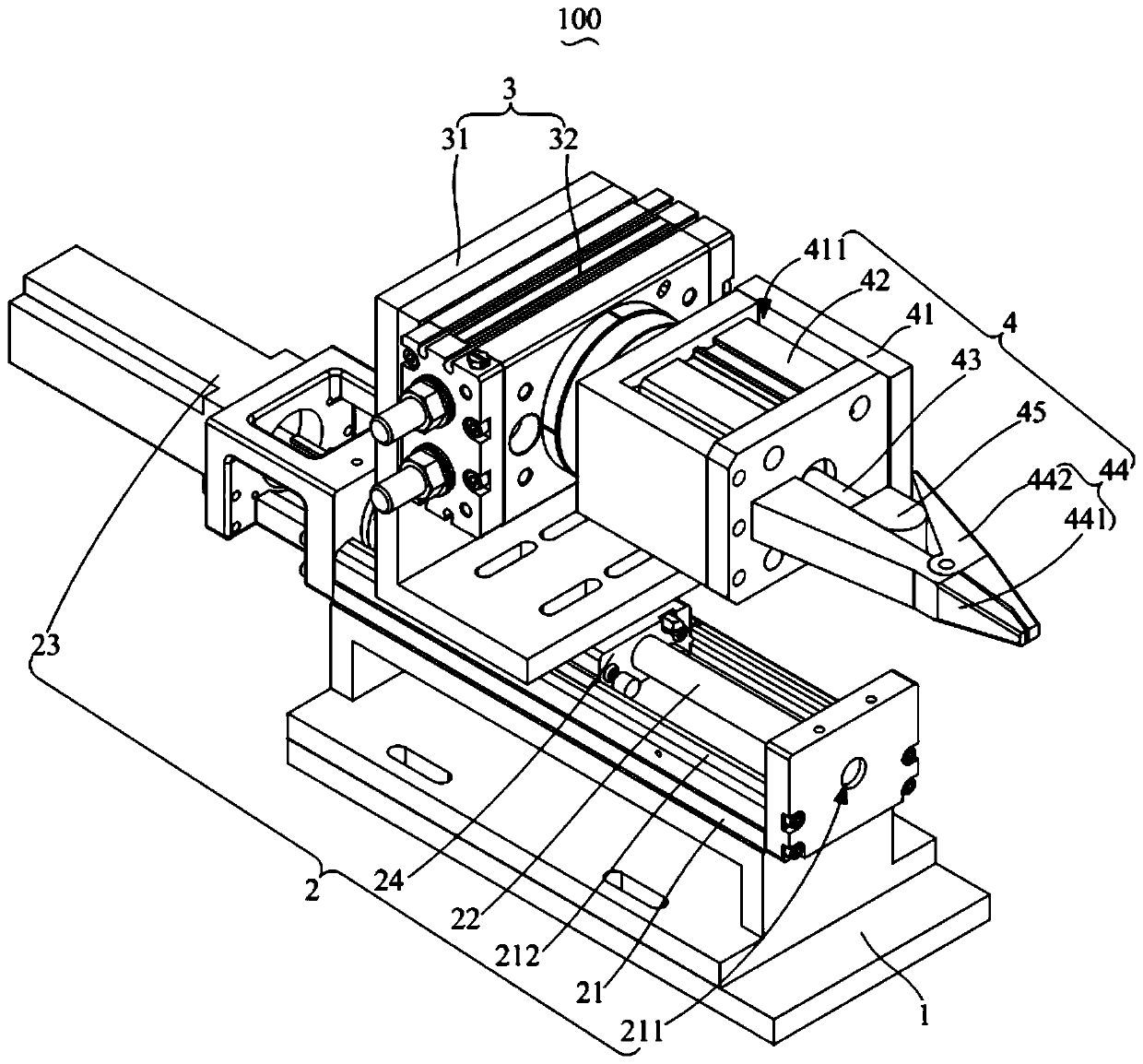
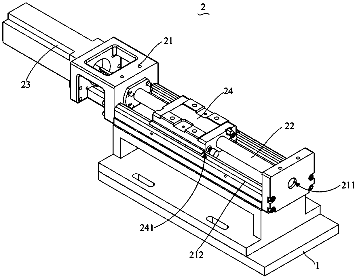
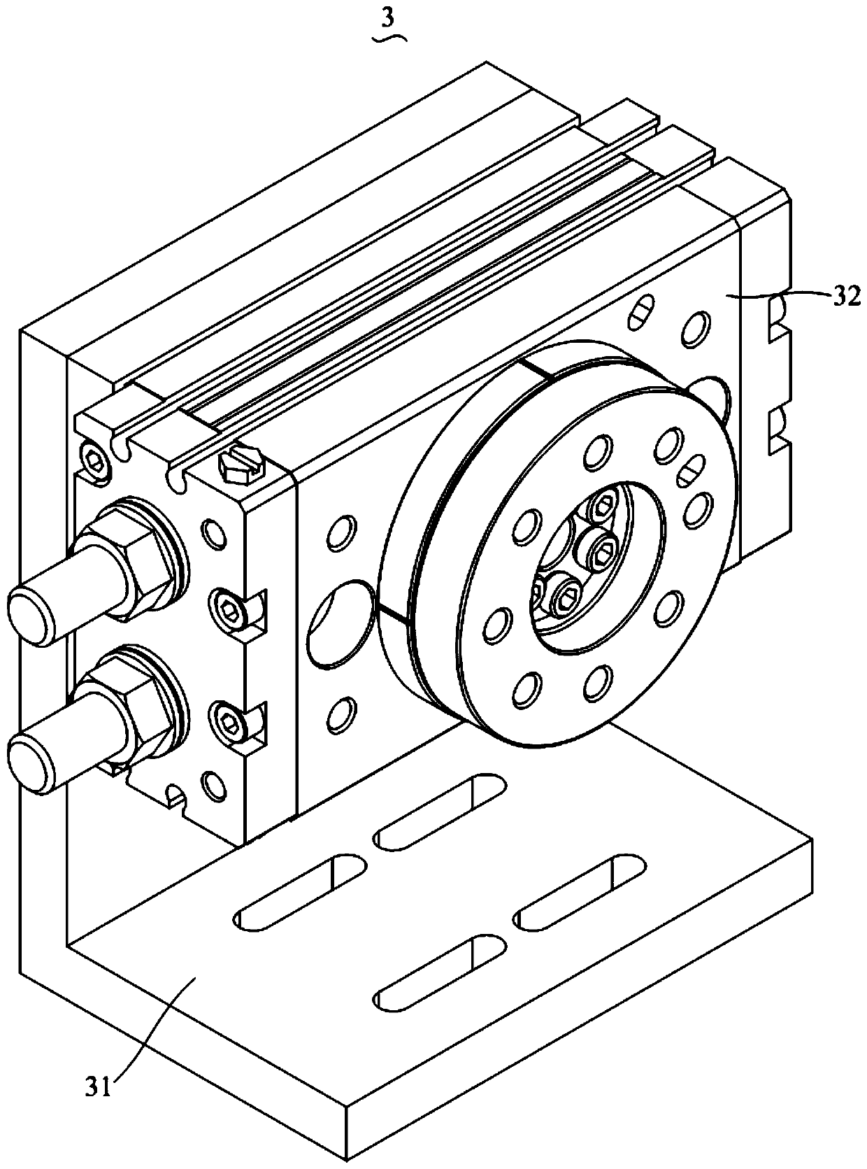
The invention discloses a discharging device used for discharging waste of a workpiece. The discharging device comprises a base, a rotating assembly and a clamping structure; the rotating assembly ismovably arranged on the base and comprises a rotating air cylinder; the clamping structure is connected with an output shaft of the rotating air cylinder and comprises a clamping head and a jacking block, the clamping head is provided with an opening and closing port and a clamping groove which are arranged in a deviating mode, and the jacking block is slidably connected with the clamping head inan abutting mode and slides in or slides out of the opening and closing port so as to enable the clamping groove to clamp or release the waste of the workpiece; and the rotating air cylinder drives the clamping structure to rotate to enable the clamping head to drive the waste to rotate relative to the workpiece to be discharged. According to the automatic discharging device, the machining efficiency is improved, the labor cost is reduced, and personnel injuring cannot occur.

Description

technical field [0001] The invention relates to the technical field of cold-shrink tube blanking equipment, in particular to a blanking device. Background technique [0002] When producing cold-shrinkable tubes, it is necessary to make a strip-shaped support frame similar to a spring in the cold-shrinkable tube. regular shape, and then thermally welded to avoid the support frame from coming off. At present, it is generally used to manually cut the support frame one by one and remove excess waste, and then weld it with a soldering iron tip, resulting in low processing efficiency of the support frame, high labor cost, and automatic production is not realized. [0003] The above is only used to assist the understanding of the technical solution of the present application, and does not mean that it is recognized as the prior art. Contents of the invention [0004] The main purpose of the present invention is to provide a blanking device, aiming to provide an automatic blanki...

Claims


Application Information

Patent Timeline
IPC IPC(8): B65G47/90
CPCB65G47/902
Inventor 杨迁张增果张维波
Owner SHENZHEN WOER HEAT SHRINKABLE MATERIAL
Learn More