Check patentability & draft patents in minutes with Patsnap Eureka AI!

Temporary fixing device for precast column of prefabricated framework structure

A frame structure and temporary fixing technology, which is applied in the on-site preparation of building components, building construction, connection parts of formwork/template/work frame, etc., can solve the problem of easy damage to the seat slurry

Active Publication Date: 2020-06-09
CHONGQING JIANZHU COLLEGE
View PDF6 Cites 1 Cited by
  • Summary
  • Abstract
  • Description
  • Claims
  • Application Information

AI Technical Summary

Problems solved by technology

[0005] The purpose of the present invention is to provide a temporary fixing device for prefabricated columns in an assembled frame structure to solve the problem in the prior art that the seat grout is easily damaged when the sleeve is grouted

Method used


Image

  • Temporary fixing device for precast column of prefabricated framework structure
  • Temporary fixing device for precast column of prefabricated framework structure
  • Temporary fixing device for precast column of prefabricated framework structure

Examples


Embodiment 1

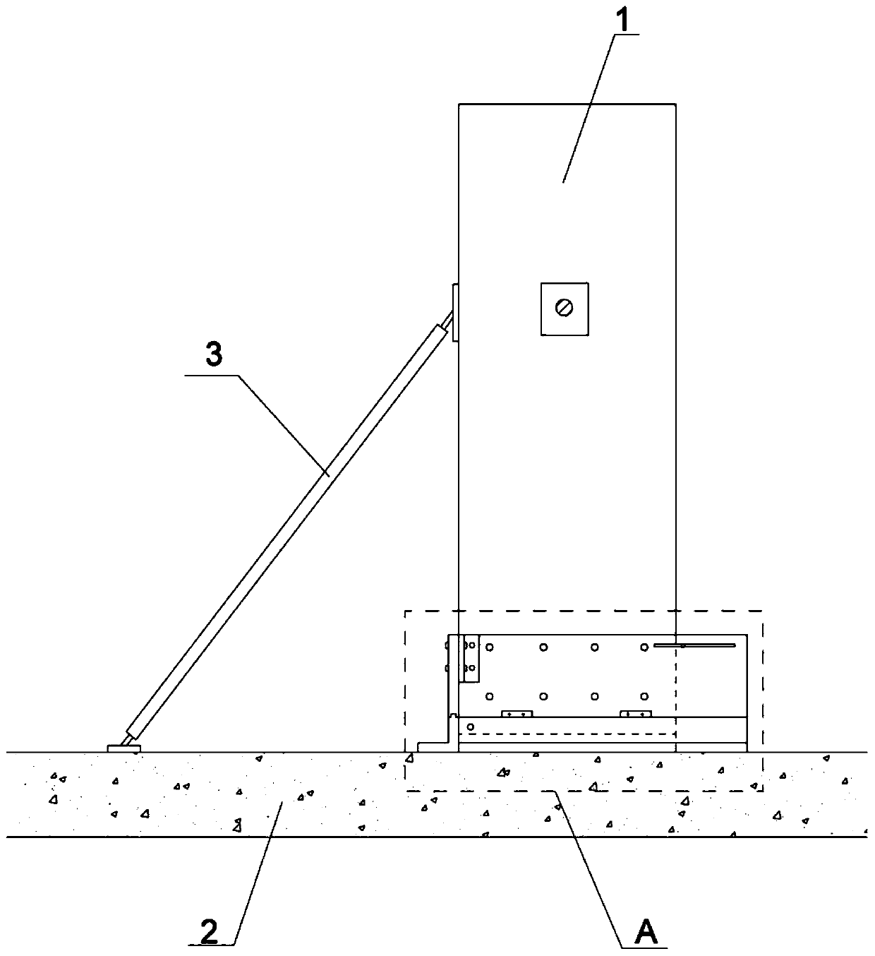
[0028] Such as figure 1 As shown, the temporary fixing device for the prefabricated column of the prefabricated frame structure in this embodiment includes a brace mechanism and a grouting mechanism.

[0029] The diagonal bracing mechanism includes a diagonal bracing rod 3. The diagonal bracing rod 3 adopts the installation and connection method of the existing prefabricated building temporary diagonal bracing, that is, one end of the diagonal bracing rod 3 is connected to the side wall of the prefabricated column 1 by a bolt, and the other end is connected by a bolt Connected to the bottom plate 2 below the prefabricated column 1 , there are two diagonal braces 3 , and the two diagonal braces 3 are respectively located on two adjacent side walls of the prefabricated column 1 .

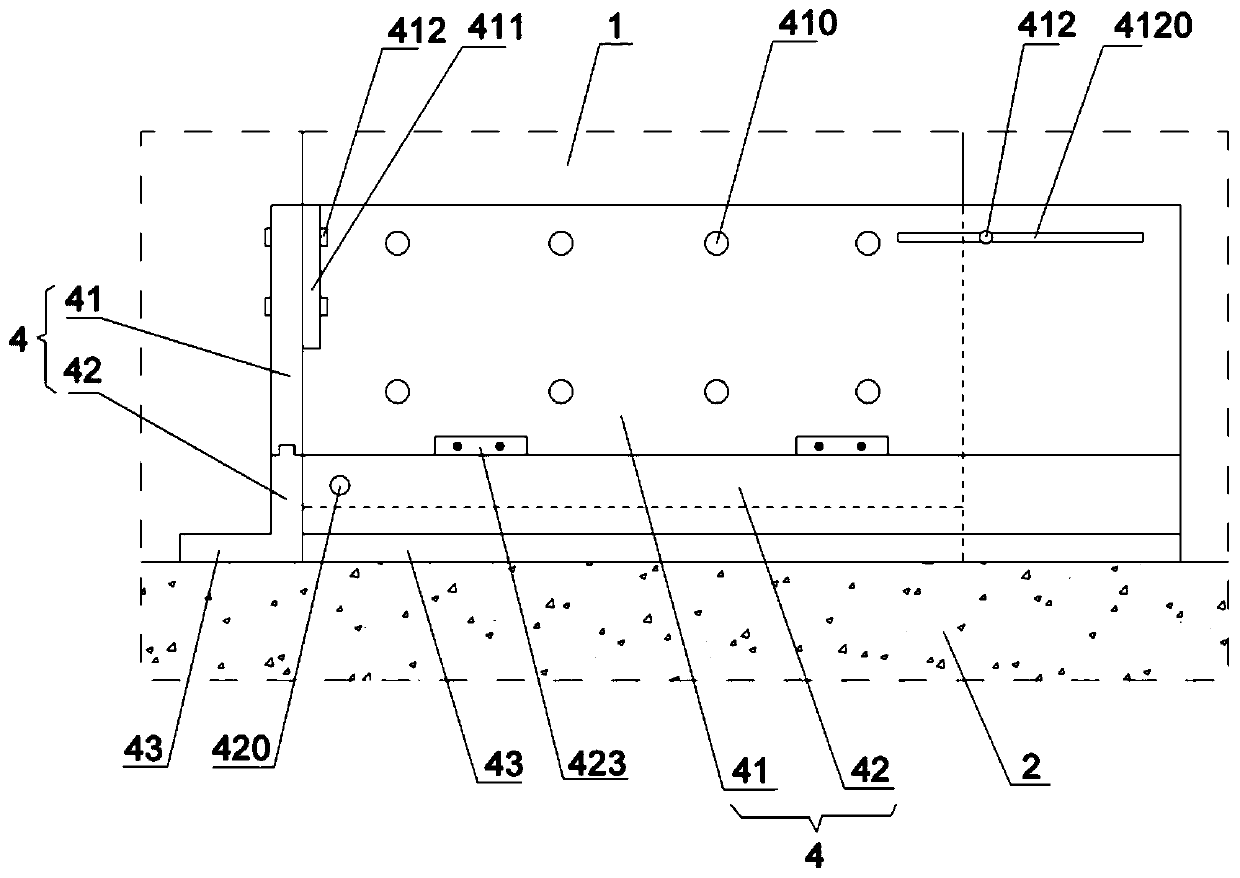
[0030] The grouting mechanism includes a plug grouting frame that can be set on the outer wall of the prefabricated column 1, and the structural combination of the plug grouting frame figure 2 with ...

Embodiment 2

[0039] The difference between this embodiment and Embodiment 1 is that in this embodiment, the locking method between the fixing plate 41 and the grouting plate 42 is different. Corresponding openings are made on the protruding strips at the top of 42, and fastening bolts 412 are used to pass through the holes on the side walls of the chute and the holes on the protruding strips to realize the connection and fixation between the fixing plate 41 and the grouting plate 42.


PUM


Abstract

The invention belongs to the field of prefabricated buildings and particularly discloses a temporary fixing device for a precast column of a prefabricated framework structure. The temporary fixing device comprises a bracing mechanism and a grouting mechanism; the grouting mechanism comprises a caulking grouting frame capable of being arranged on the outer wall of the precast column in a sleeving manner, the caulking grouting frame is spliced by four splice plates, the four splice plates are attached to four outer walls of the precast column respectively, the inner ends of the splice plates areflush with edges of the precast column, the outer ends extend out of the precast column, each splice plate comprises a fixed plate and a grouting plate connected onto the fixed plate in a sliding manner, the grouting plate is located below the fixed plate, a grouting hole corresponding to a grouting opening of the precast column is formed in the fixed plate, the grouting plate covers a gap between the bottom of the precast column and a bottom plate, a bed mortar hole is formed in the grouting plate, and a mortar collecting plate attached to the bottom plate below the precast column is connected with the bottom of the grouting plate. With the adoption of the temporary fixing device, the problem that bed mortar is easily damaged during sleeve grouting in the prior art can be solved.

Description

technical field [0001] The invention relates to the field of prefabricated buildings, in particular to a temporary fixing device for a prefabricated column of an assembled frame structure. Background technique [0002] The prefabricated frame structure is one of the most widely used structural forms at present. It has the characteristics of flexible building layout, large use space, easy separation, and good ductility. At present, it is widely used in prefabricated construction projects. The main project of the prefabricated frame structure is the structural installation project. The frame structure column section is generally square or rectangular. The hoisting process is: measurement and setting out → component on-site inspection → component numbering → spreader installation → turning upright → lifting → steel bar pairing In place→In place→Install temporary braces→Adjust grouting. The purpose of installing temporary diagonal braces is to adjust the verticality and leveln...

Claims


Application Information

Patent Timeline
IPC IPC(8): E04G21/26E04G21/18E04G21/02E04G17/00
CPCE04G21/26E04G21/1841E04G21/02E04G17/002E04G17/005
Inventor 武新杰钟焘丁王飞曾虹季翠华
Owner CHONGQING JIANZHU COLLEGE
Features
  • R&D
  • Intellectual Property
  • Life Sciences
  • Materials
  • Tech Scout
  • Unparalleled Data Quality
  • Higher Quality Content
  • 60% Fewer Hallucinations
Learn More