
Rail vehicle shock absorber

A rail vehicle and shock absorber technology, which is applied in the direction of shock absorbers, liquid shock absorbers, shock absorbers, etc., can solve the problems of improving work efficiency, high noise, disadvantages, etc., and achieves the reduction of fuel injection noise and damping force value Stable and improve the effect of regulation efficiency

Active Publication Date: 2020-06-09
CRRC CHANGZHOU DIESEL ENGINE COMPONENTS CO LTD +1
View PDF9 Cites 0 Cited by
  • Summary
  • Abstract
  • Description
  • Claims
  • Application Information

AI Technical Summary

Problems solved by technology

In order to reduce the vibration frequency and amplitude and improve the safety of EMU operation, the use of hydraulic shock absorbers in EMUs is becoming more and more extensive. However, due to design reasons, the existing shock absorbers can only The adjustment of the valve system is relatively complicated, which is not conducive to improving work efficiency, and the noise is relatively large, which is contrary to the concept of vibration reduction and noise reduction

Method used


Image

  • Rail vehicle shock absorber
  • Rail vehicle shock absorber
  • Rail vehicle shock absorber

Examples


Embodiment 1

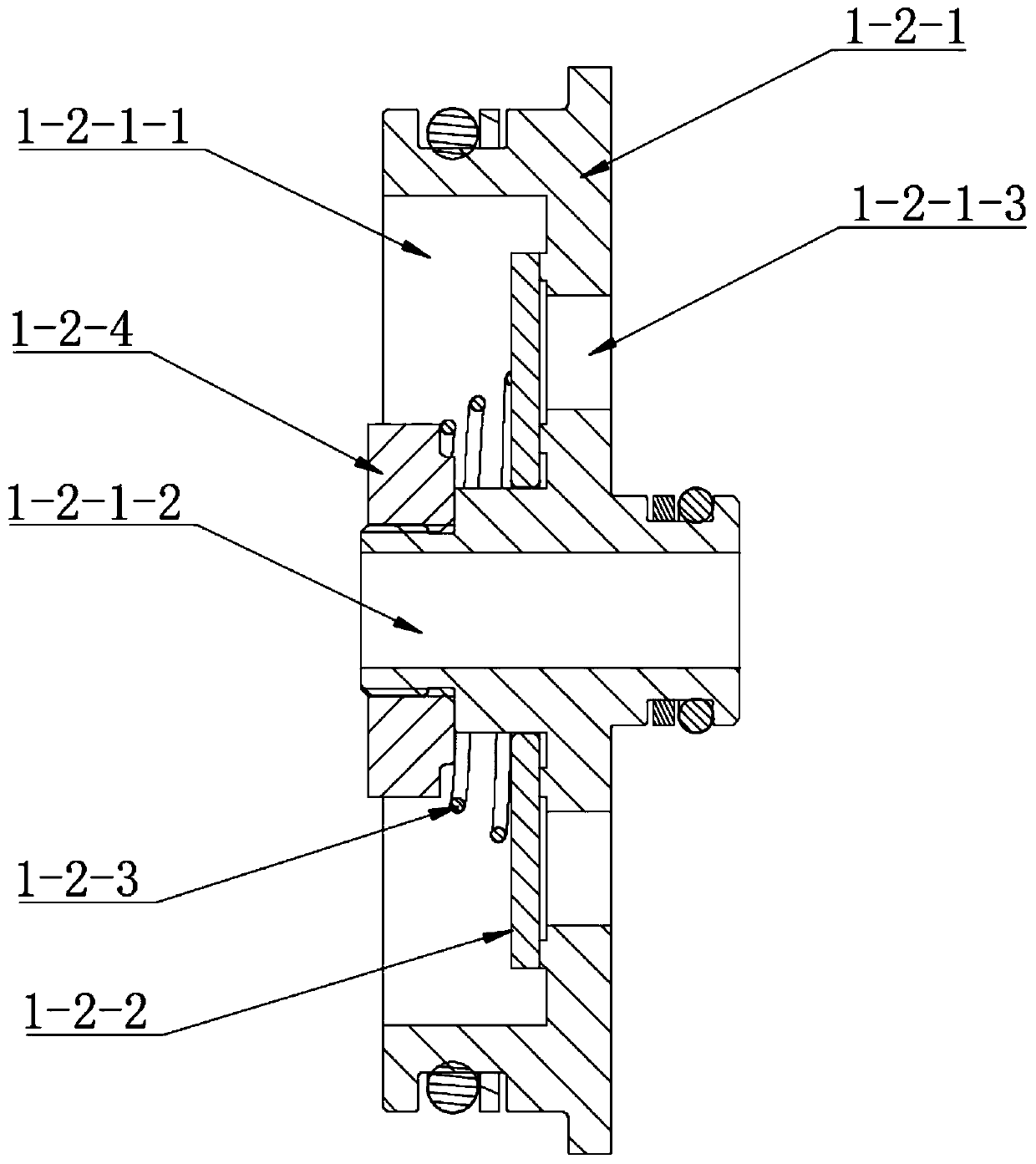
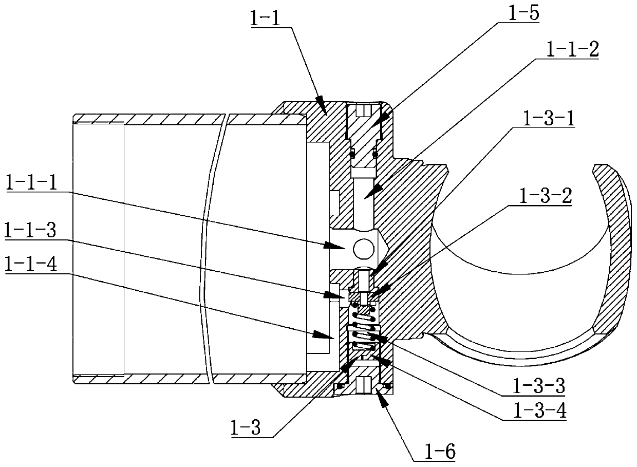
[0063] See figure 1 , The railway vehicle shock absorber of this embodiment includes a base assembly 1, an oil storage cylinder 2, an oil cylinder 3, an end cover assembly 4, a piston assembly 5, a piston rod assembly 6 and a rubber joint 7.

[0064] One end of the oil storage cylinder 2 is sealed and fixed to the inner end of the base assembly 1 . The oil cylinder 3 is arranged in the oil storage cylinder 2 , and one end of the oil cylinder 3 is in sealing connection with the inner end of the base assembly 1 . The end cover assembly 4 is in sealing connection with the other end of the oil cylinder 3 and the oil storage cylinder 2 . The piston assembly 5 is arranged in the oil cylinder 3 and is in sealing and sliding connection with the inner wall of the oil cylinder 3 . The piston rod assembly 6 runs through the end cover assembly 4 and is in sealing and sliding connection with the end cover assembly 4 . The inner end of the piston rod assembly 6 is fixedly connected with ...


PUM


Abstract

The invention discloses a rail vehicle shock absorber. The rail vehicle shock absorber comprises a base assembly, an oil cylinder, an end cover assembly, a piston assembly and a piston rod assembly. An oil storage oil cylinder is fixed to the inner end of the base assembly in a sealed manner. The oil cylinder is arranged in the oil storage cylinder, and one end of the oil cylinder is fixedly connected with the inner end of the base assembly in a sealed manner. The end cover assembly is fixedly connected with the other ends of the oil cylinder and the oil storage cylinder in a sealed manner. The piston assembly is arranged in the oil cylinder and is in sealed sliding connection with the inner wall of the oil cylinder. The piston rod assembly penetrates the end cover assembly and is in sealed sliding connection with the end cover assembly. The inner end of the piston rod assembly is fixedly connected with the piston assembly. Rubber joints fixedly connected with the piston rod assembly and the base assembly are correspondingly arranged at the outer ends of the piston rod assembly and the base assembly. Damping valves capable of adjusting the resistance from the outer side are correspondingly arranged on the base assembly and the end cover assembly. According to the rail vehicle shock absorber, the damping valves capable of adjusting the resistance from the outer side are correspondingly arranged on the base assembly and the end cover assembly, the adjustment is quite convenient, and it is not necessary to disassemble the whole shock absorber, so that the adjusting efficiencyof the damping force of the valve system can be greatly increased.

Description

technical field [0001] The invention relates to a rail vehicle shock absorber. Background technique [0002] When the EMU is running, due to the stimulation of various factors, there will inevitably be interactions between the vehicles and the track, and between the various vehicles of the EMU, and the horizontal and vertical unbalanced forces will be generated through the interaction. In addition, during the manufacturing process, the rails cannot be absolutely straight and rigid, and the wheels of the EMU cannot be ideally round. It is precisely because of this unbalanced force and manufacturing error that the EMU will present complex motion laws when running along the rails, so vibration will inevitably occur, which will affect the operation safety of the EMU and the comfort of passengers. have an important impact. In order to reduce the vibration frequency and amplitude and improve the safety of EMU operation, the use of hydraulic shock absorbers in EMUs is becoming mo...

Claims


Application Information

Patent Timeline
Patent Type & Authority Applications(China)
IPC IPC(8): F16F9/19F16F9/32F16F9/34F16F9/44
CPCF16F9/19F16F9/3214F16F9/3242F16F9/34F16F9/341F16F9/446F16F2230/0005
Inventor 刘畅庞林春陈春鹏周小智方照根
Owner CRRC CHANGZHOU DIESEL ENGINE COMPONENTS CO LTD
Learn More