A dual laser robot joint angle measurement method and angle measurement device

An angle measuring device and a technology of robot joints, which are applied in the direction of measuring devices, optical devices, instruments, etc., can solve the problems of inability to guarantee the attitude measurement of robot joints, inability to adapt to production application scenarios, and insufficient dynamic range, so as to reduce errors , Inexpensive, Reliable Measuring Effects

Active Publication Date: 2021-06-04
TONGJI UNIV
View PDF9 Cites 0 Cited by
  • Summary
  • Abstract
  • Description
  • Claims
  • Application Information

AI Technical Summary

Problems solved by technology

These methods can achieve very high angle measurement accuracy, but the dynamic range of the measurement is small, and the cost is relatively high due to the precision processing of optical components and the complexity of the optical path.
Recently, a non-contact angle measurement device based on the laser triangulation method has been designed. This method has a large dynamic range and fast response speed, but the optical path of the device is complicated and the equipment cost is still high.
[0011] To sum up, the existing angle measurement devices are either difficult to install, or have insufficient dynamic range, or are expensive, and cannot meet the requirements for robot joint attitude measurement, and cannot adapt to complex production application scenarios.

Method used


Image

  • A dual laser robot joint angle measurement method and angle measurement device
  • A dual laser robot joint angle measurement method and angle measurement device
  • A dual laser robot joint angle measurement method and angle measurement device

Examples


Embodiment 1

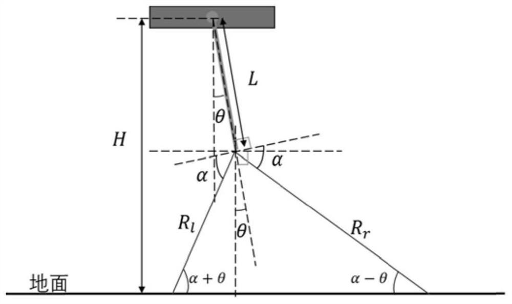
[0054]This embodiment provides a method for measuring the joint angle of a dual laser robot. The method uses the ground plane as a reference plane to construct a laser-plane angle measurement model, and converts the rotation angle of the joint by converting the geometric relationship between the laser distance measurement and the rotation angle of the joint. The angle change is converted into the laser ranging change. During real-time measurement, the rotation angle of the robot joint is obtained by measuring the dual laser ranging change value at the robot joint and the laser-plane angle measuring model. The method includes the following steps:

[0055] 1) A dual laser range finder is installed on the robot. The dual laser range finder includes two dual lasers, and the angle between the outgoing laser of the laser and the vertical direction of the arm axis is set according to the measurement requirements;

[0056] 2) Real-time acquisition of the left and right laser ranging v...

Embodiment 2

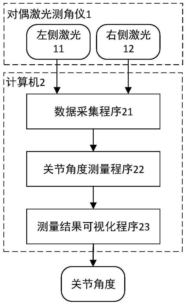
[0087] like figure 1 As shown, this embodiment provides a dual laser type robot joint angle measurement device, including a dual laser range finder 1 and a computer 2, wherein the dual laser range finder 1 is installed on the robot, and its central axis is the same as the arm axis of the robot. Parallel; the computer 2 is connected to the dual laser rangefinder, collects the left and right laser distance measurement values ​​of the dual laser rangefinder in real time during the movement of the robot joint, and obtains the rotation angle of the robot joint based on the laser-plane angle measurement model. The measurement principle of the angle measurement device is as in Embodiment 1.

[0088] The dual laser rangefinder 1 can be installed in the axial direction of the robot arm, such as at the end of the robot or on the side of the robot arm, as long as it is parallel to the movement direction.

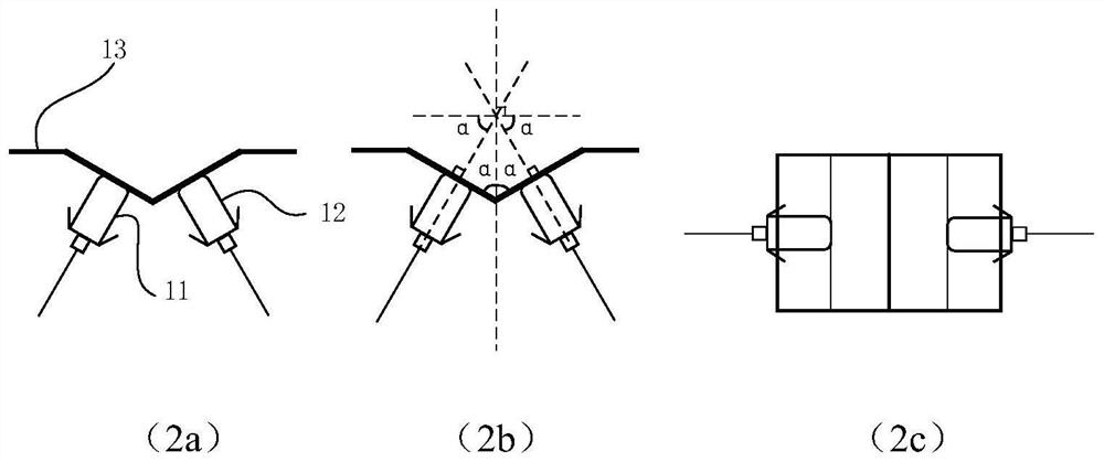
[0089] like figure 2 As shown, the dual laser rangefinder includes a V-shaped b...


PUM


Abstract

The invention relates to a dual laser robot joint angle measurement method and an angle measurement device. The measurement method uses the ground plane as a reference plane to construct a laser-plane angle measurement model, and obtains the range measurement value of a pair of dual lasers at the robot joint by measuring the change value of the dual laser distance measurement method. The rotation angle of the robot joint; the measuring device includes a dual laser range finder, which is installed on the robot, and its central axis is parallel to the arm axis of the robot; the computer is connected with the dual laser range finder, and during the movement of the robot joint The left and right laser ranging values ​​of the dual laser range finder are collected in real time, and the rotation angle of the robot joint is obtained based on the laser-plane angle measurement model. Compared with the prior art, the invention has the advantages of high measurement accuracy, simplicity and the like.

Description

technical field [0001] The invention relates to the technical field of robot joint angle measurement, in particular to a dual laser type robot joint angle measurement method and an angle measurement device. Background technique [0002] Joint angle measurement is an important part of the robot motion control process. Many scenes in industrial production and daily life need to measure the joint angle, such as the joint angle of a multi-axis robot, the opening and closing angles of automatic rotating doors and windows, etc. Usually, various goniometer sensors convert the angular displacement in the movement of the mechanism into an electrical signal. After the computer receives the data, it obtains the joint angle value of the mechanism through certain mathematical operations, so as to determine the joint movement position to provide feedback for the controller. refer to. [0003] In recent years, with the development of computer technology and the improvement of sensor perfo...

Claims


Application Information

Patent Timeline
Patent Type & Authority Patents(China)
IPC IPC(8): G01B11/26
CPCG01B11/26
Inventor 陈启军杜孝国刘成菊
Owner TONGJI UNIV
Why Eureka
Try Eureka