
Backdrill inspection method, system and device and medium

An inspection method and back-drilling technology, applied in CAD circuit design, electronic circuit testing, measuring devices, etc., can solve the problems of heavy workload, affecting the attention of inspectors and the quality of inspection, product failure and repetition, etc. The effect of success, avoiding a lot of mistakes, improving work efficiency

Active Publication Date: 2020-06-09
SUZHOU LANGCHAO INTELLIGENT TECH CO LTD
View PDF1 Cites 3 Cited by
  • Summary
  • Abstract
  • Description
  • Claims
  • Application Information

AI Technical Summary

Problems solved by technology

[0004] After completing the back-drilling settings, in order to avoid design failure due to errors such as missed settings or wrong back-drilling settings, the designer often needs to spend several times the manpower and time spent on checking the generated back-drilling photopainting layer , the designer needs to manually check each via on each high-speed line of the back-drilling repeatedly. The inspection items include but are not limited to back-drilling the start layer and termination layer, retaining the stub length and other attributes, so if there are 1000 vias The network needs to be back-drilled. There are at least two layer-changing vias on each network. The designer has at least 1000*2*3=6000 inspection items to pay attention to. This workload is huge, and even a skilled engineer must at least Spending hours on inspection and repeating a huge workload will affect the inspector's attention and the quality of inspection, and such a mistake will lead to product failure and repeated

Method used


Image

  • Backdrill inspection method, system and device and medium
  • Backdrill inspection method, system and device and medium
  • Backdrill inspection method, system and device and medium

Examples


Embodiment Construction

[0049] In order to make the object, technical solution and advantages of the present invention clearer, the embodiments of the present invention will be further described in detail below in conjunction with specific embodiments and with reference to the accompanying drawings.

[0050] It should be noted that all expressions using "first" and "second" in the embodiments of the present invention are to distinguish two entities with the same name but different parameters or parameters that are not the same, see "first" and "second" It is only for the convenience of expression, and should not be construed as a limitation on the embodiments of the present invention, which will not be described one by one in the subsequent embodiments.

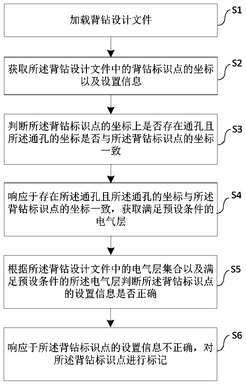
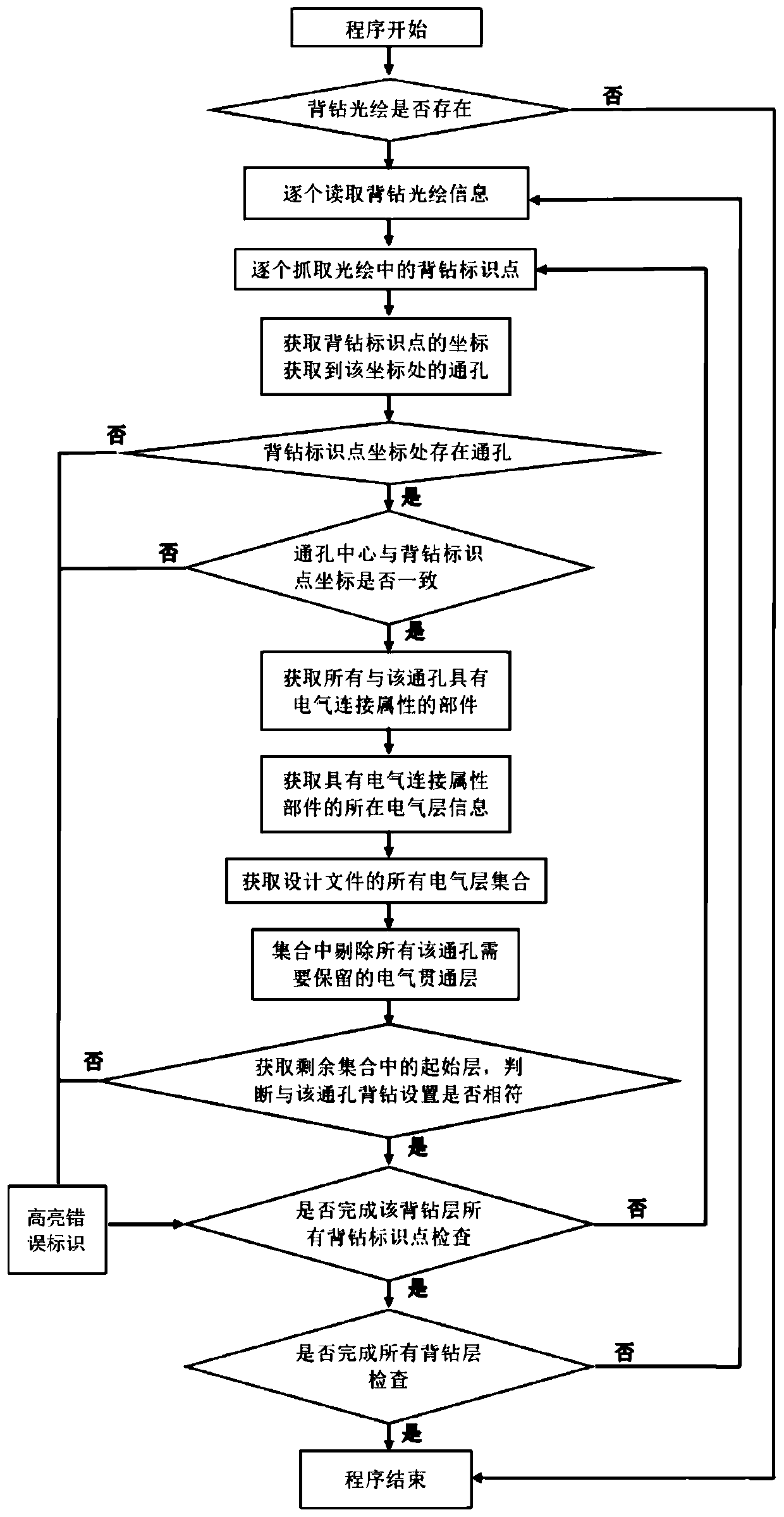
[0051] According to one aspect of the present invention, the embodiment of the present invention proposes a backdrill inspection method, such as figure 1 As shown, it may include the steps: S1, loading the back drilling design file; S2, obtaining th...


PUM


Abstract

The invention discloses a backdrill inspection method. The backdrill inspection method comprises steps of loading a backdrill design file; acquiring coordinates and the setting information of a backdrill identification point in the backdrill design file; judging whether a through hole exists in the coordinates of the backdrill identification point and whether coordinates of the through hole are consistent with the coordinates of the backdrill identification point; in response to the fact that the through hole exists and the coordinates of the through hole are consistent with the coordinates ofthe backdrill identification point, obtaining an electrical layer meeting a preset condition; judging whether the setting information of the backdrill identification point is correct or not accordingto the electrical layer set in the backdrill design file and the electrical layer meeting the preset condition; and marking the backdrill identification point in response to the incorrect setting information of the backdrill identification point. The invention further discloses a system, computer equipment and a readable storage medium. The backdrill inspection method all the identification points on all the backdrill light painting layers on the PCB can be automatically checked one by one, so working efficiency is greatly improved.

Description

technical field [0001] The invention relates to the field of software detection, in particular to a method, system, equipment and storage medium for backdrilling inspection. Background technique [0002] Usually, some high-speed signal interconnection protocols will make requirements for the above elements in the link that may affect the signal integrity, so that the passive link can meet the corresponding rate requirements. Among them, the optimization of vias is the top priority, and via back drilling is the most effective and direct method to improve signal integrity. Therefore, the high-speed signals on current high-speed PCB boards such as switches and servers Back drilling has become a must. [0003] Since back drilling is to carry out "secondary drilling" on the basis of the original drilling, so, like the design of through holes, when the board factory is back drilling, it is necessary for the PCB designer to provide the drilling diagram of the back drilling, that i...

Claims


Application Information

Patent Timeline
IPC IPC(8): G01R31/28G06F30/39B26D5/00
CPCG01R31/2806B26D5/00B26F2210/08
Inventor 郑家雄侯绍铮
Owner SUZHOU LANGCHAO INTELLIGENT TECH CO LTD
Learn More