Method for restraining deformation of existing cutting gravity type retaining wall

A gravity-type retaining wall technology, applied in buildings, artificial islands, geometric CAD, etc., can solve the problems of not considering the bearing capacity of existing cutting gravity-type retaining walls and low economic efficiency, so as to avoid demolition and reconstruction and improve economic efficiency , the effect of quick disturbance

Active Publication Date: 2020-06-09
CHINA RAILWAY ERYUAN ENG GRP CO LTD
View PDF10 Cites 5 Cited by
  • Summary
  • Abstract
  • Description
  • Claims
  • Application Information

AI Technical Summary

Problems solved by technology

[0006] The purpose of the present invention is to overcome the problem existing in the prior art that the carrying capacity of the existing gravity retaining wall of the cutting is not considered when reinforcing the existing gravity retaining wall of the cutting, which leads to low economic efficiency. The existing cutting gravity retaining wall deformation method improves economy and saves engineering investment under the premise of ensuring safety

Method used


Image

  • Method for restraining deformation of existing cutting gravity type retaining wall
  • Method for restraining deformation of existing cutting gravity type retaining wall
  • Method for restraining deformation of existing cutting gravity type retaining wall

Examples


Embodiment 1

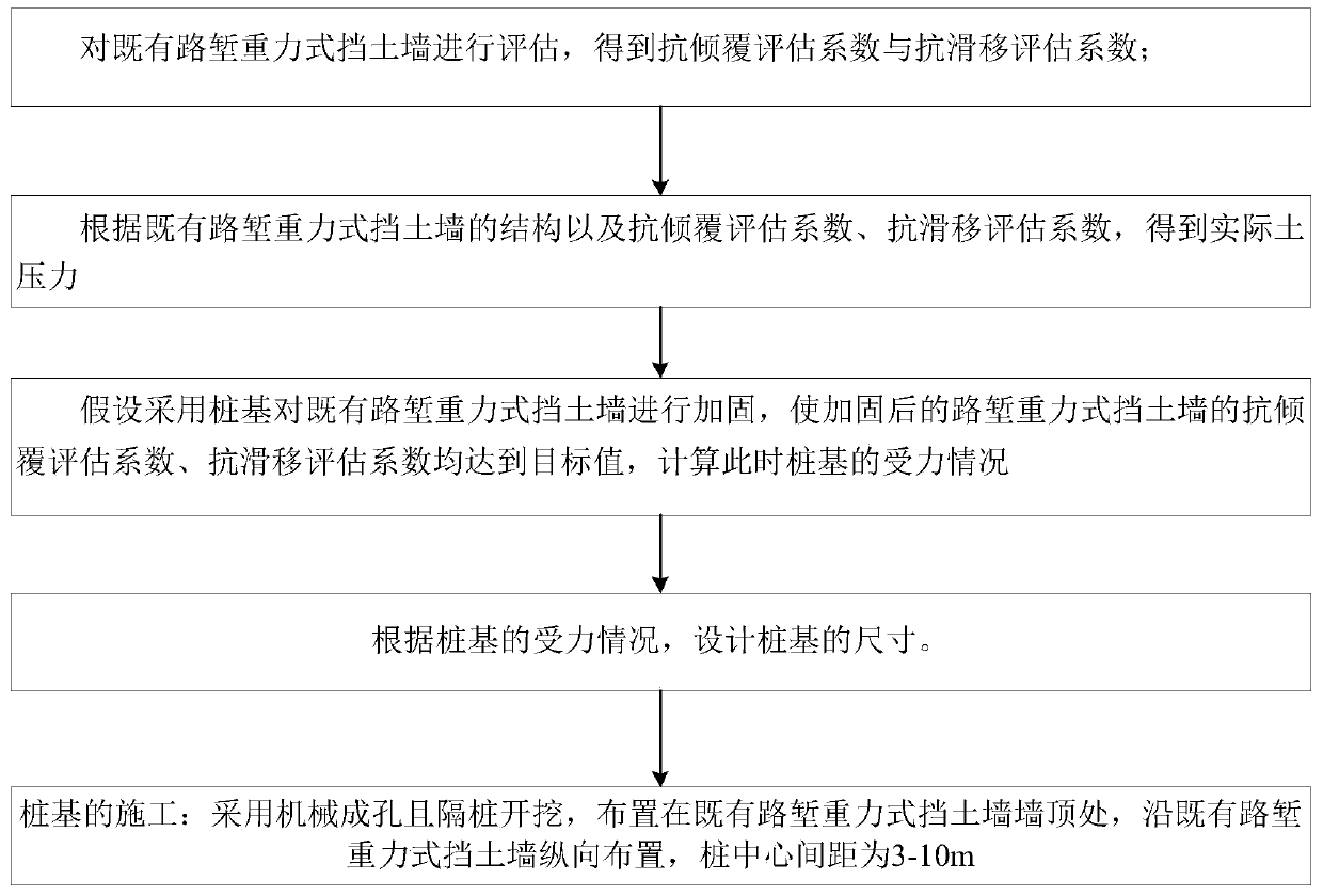
[0058] Such as figure 1 , a method for suppressing deformation of an existing cutting gravity retaining wall 1, comprising:

[0059] S100 evaluates the existing cutting gravity retaining wall 1 to obtain the actual anti-overturning evaluation coefficient and the actual anti-sliding evaluation coefficient;

[0060] S200 Obtain the actual earth pressure according to the structural force of the existing cutting gravity retaining wall 1, the actual overturning resistance evaluation coefficient, and the actual anti-slip evaluation coefficient;

[0061] S300 assumes that pile foundations are used to reinforce the existing gravity retaining wall 1 of the cutting, so that the target anti-overturning evaluation coefficient and target anti-slip evaluation coefficient of the reinforced cutting gravity retaining wall can be used to calculate the stress of the pile foundation;

[0062] S400 designs the size of the pile foundation according to the force condition of the pile foundation.

...

Embodiment 2

[0140] The first step is to evaluate the gravity retaining wall 1 of the existing road cutting

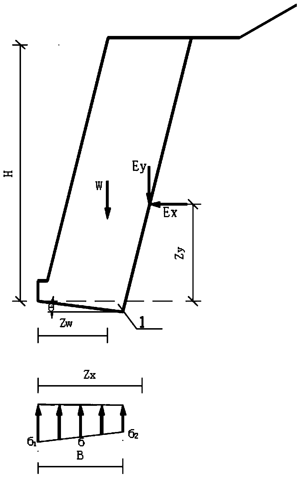
[0141] Such as Figure 7 , it is known that there is an existing cut gravity retaining wall 1 of a single-line Class I railway, the retaining wall is 6.0m high and 1.4m buried deep. The back slope slope is 1:-0.25, the wall toe step width is 0.25m, the wall toe step height is 0.6m, the wall toe step is the same as the wall slope, the wall bottom slope ratio is 0.200:1, and the base friction coefficient f is 0.3, see for details Image 6 . The original design anti-overturning stability safety factor is 2.1847, and the original design anti-sliding stability safety factor is 1.316.

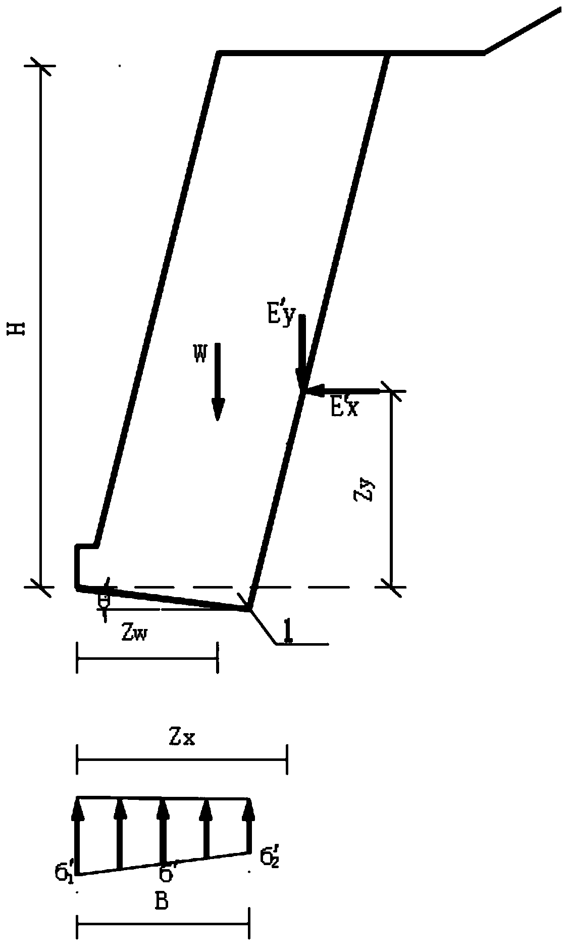
[0142] According to the safety assessment method and means, the anti-overturning and anti-sliding stability of the existing cutting gravity retaining wall 1 is evaluated, and the anti-overturning and anti-sliding evaluation coefficients K are respectively obtained 02 = 1.5 and K C2 = 1.1.

[0143] T...


PUM


Abstract

The invention discloses a method for restraining deformation of an existing cutting gravity type retaining wall. The partial bearing capacity still reserved by the existing cutting gravity type retaining wall is fully considered; a row of drilling piles are arranged behind the wall; the soil pressure of the existing cutting gravity type retaining wall is reduced; the anti-sliding and anti-overturning safety of the structure is improved; the sizes of the pile foundations are designed according to the stress of the existing cutting gravity type retaining wall and the stress of the newly-built pile foundations; compared with the prior art, the brand-new calculation design method considering the bearing effect of the existing cutting gravity type retaining wall is provided, dismantling and rebuilding of the existing retaining wall are avoided, the load shared by pile foundations is reduced, the sizes of the pile foundations are optimized, and therefore on the premise that safety is guaranteed, engineering investment is reduced, and economical efficiency is improved.

Description

technical field [0001] The invention relates to the technical field of geotechnical engineering, in particular to a method for suppressing the deformation of an existing road cutting gravity retaining wall. Background technique [0002] In the construction of infrastructure such as railways and highways, gravity retaining walls are widely used in road cutting excavation sections. The nature of the rock and soil behind the gravity retaining wall of the cutting is complex. During actual use, due to natural factors such as earthquakes, rain erosion, changes in geological conditions, and human factors in early construction, the gravity retaining wall has a certain sliding deformation or The disease of outward tilting deformation leads to a decrease in the stability of the gravity retaining wall against slipping or overturning, and the risk of slipping and overturning damage may occur after long-term use. [0003] Although the gravity retaining wall has a certain sliding deforma...

Claims


Application Information

Patent Timeline
Patent Type & Authority Applications(China)
IPC IPC(8): G06F30/13G06F30/20E02D29/02E02D27/12G06F119/14
CPCE02D29/02E02D27/12
Inventor 魏永幸吴邵海刘菀茹王智猛周波付正道褚宇光
Owner CHINA RAILWAY ERYUAN ENG GRP CO LTD
Why Eureka
Try Eureka