Fire extinguishing device for power distribution cabinet

A technology of fire extinguishing device and power distribution cabinet, which is applied in substation/power distribution device shell, fire rescue, medical science, etc. It can solve the problems that affect the service life of electronic components in the power distribution cabinet, easily cause fire, and have high danger

Active Publication Date: 2020-06-09
山东华控自动化设备有限公司
View PDF11 Cites 9 Cited by
  • Summary
  • Abstract
  • Description
  • Claims
  • Application Information

AI Technical Summary

Problems solved by technology

[0003] There are a large number of transmission circuits and electronic components inside the power distribution cabinet. When they are in working condition, high heat will be generated in the power distribution cabinet. Long-term high temperature will affect the service life of electronic components in the power distribution cabinet, especially in the In summer, the high temperature inside the power distribution cabinet is more likely to cause a fire. Most of the traditional fire extinguishing methods are to open the door of the power distribution cabinet and then use a fire extinguisher to directly extinguish the fire. However, a large amount of air will enter the power distribution cabinet at the moment the door is opened. Inside, it is easy to make the fire more fierce and dangerous

Method used


Image

  • Fire extinguishing device for power distribution cabinet
  • Fire extinguishing device for power distribution cabinet
  • Fire extinguishing device for power distribution cabinet

Examples


Embodiment 1

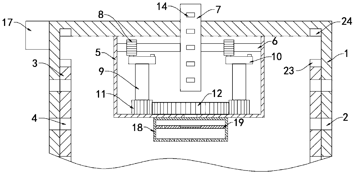
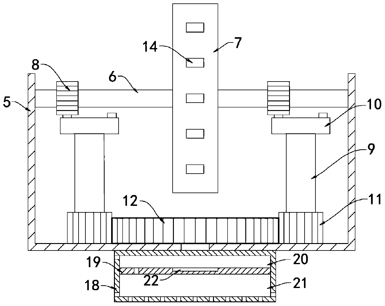
[0026] like Figure 1-3 As shown, a fire extinguishing device for a power distribution cabinet includes a cabinet body 1, and a plurality of evenly arranged outer ventilation holes 2 are arranged on the side wall of the cabinet body 1. It is worth mentioning that the cabinet body 1 is provided with a power supply The disconnector 17, when the power disconnector 17 detects that there is a fire inside the cabinet body 1, it will cut off the power supply of the entire power distribution cabinet at the first time, which can effectively prevent the fire from spreading along the circuit.

[0027] The inner side wall of the cabinet body 1 is slidably connected with an insulating plate 3, and the insulating plate 3 is provided with a plurality of evenly arranged inner air holes 4, and a plurality of outer air holes 2 and a plurality of inner air holes 4 are connected one by one. In this state, the connected outer air holes 2 and inner air holes 4 can make the entire power distribution...

Embodiment 2

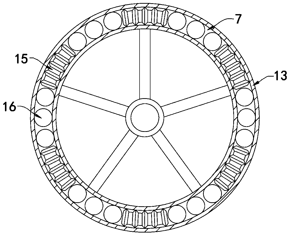
[0044] like Figure 4 As shown, the difference between this embodiment and Embodiment 1 is that a sliding cavity 25 is provided in the upper side wall of the cabinet body 1, one end of the sliding cavity 25 communicates with the perforation, and the other end of the sliding cavity 25 communicates with the magnetic block 24. Correspondingly, the sliding cavity 25 is slidably connected with a magnetic strip 26 , and the magnetic strip 26 is the same as the magnetism of the permanent magnet 23 .

[0045] In this embodiment, when the temperature does not reach the Curie point of the magnetic block 24, the magnetic block 24 and the magnetic strip 26 repel each other with opposite poles, so the end of the magnetic strip 26 away from the magnetic block 24 will extend into the perforated hole under normal conditions to drive Wheel 7 carries out spacing, when breaking out of fire in cabinet body 1, when temperature reaches magnetic block 24 curie points, magnetic block 24 can demagneti...


PUM


Abstract

The invention belongs to the field of fire extinguishing equipment and relates to a fire extinguishing device for a power distribution cabinet. The cabinet comprises a cabinet body; a plurality of outer air holes which are uniformly distributed are formed in the side wall of the cabinet body; the inner side wall of the cabinet body is connected with an isolation plate in a sliding manner; a plurality of uniformly distributed inner air holes are formed in the isolation plate; the plurality of outer air holes are communicated with the plurality of inner air holes one by one; the inner top surface of the cabinet body is fixedly connected with a heat conduction box; a rotating shaft which is horizontally arranged is rotationally connected into the heat conduction box; a driving wheel and two driving gears are fixedly arranged on the rotating shaft in a sleeving mode; the two driving gears are arranged on the two sides of the driving wheel respectively; two vertically-arranged rotating rodsare arranged in the heat conduction box; and crown gears connected with the driving gears in an engaged mode are fixedly connected to the upper ends of the two rotating rods. When a fire occurs in the power distribution cabinet, an extrusion plate in a rotating box can continuously move up and down when the driving wheel rotates, so that a fire extinguishing solution in a lower cavity can be sprayed into the cabinet body to extinguish the fire.

Description

technical field [0001] The invention belongs to the field of fire extinguishing equipment, in particular to a fire extinguishing device for a power distribution cabinet. Background technique [0002] The power distribution cabinet is the final equipment of the power distribution system. It is the general name of the motor control center. It distributes the electric energy of a certain circuit of the upper-level power distribution equipment to the nearest load, and plays the role of regulating multiple circuits. [0003] There are a large number of transmission circuits and electronic components inside the power distribution cabinet. When they are in working condition, high heat will be generated in the power distribution cabinet. Long-term high temperature will affect the service life of electronic components in the power distribution cabinet, especially in the In summer, the high temperature inside the power distribution cabinet is more likely to cause a fire. Most of the t...

Claims


Application Information

Patent Timeline
Patent Type & Authority Applications(China)
IPC IPC(8): H02B1/28A62C3/16A62C31/00A62C2/04
CPCA62C2/04A62C3/16A62C31/00H02B1/28
Inventor 邓智超王珂欣
Owner 山东华控自动化设备有限公司
Why Eureka
Try Eureka