
Buck-boost DC-DC converter and control method

A technology of DC-DC and converters, which is applied in the field of buck-boost DC-DC converters and control, which can solve problems such as complex control of buck-boost converters, and achieve smooth switching, simple control, current ripple and voltage ripple. small wave effect

Active Publication Date: 2020-06-09
SOUTHCHIP SEMICON TECH SHANGHAI CO LTD
View PDF10 Cites 10 Cited by
  • Summary
  • Abstract
  • Description
  • Claims
  • Application Information

AI Technical Summary

Problems solved by technology

[0003] The control of the existing buck-boost converter in the BUCK-BOOST mode is relatively complicated, and there is still room for optimization in the switching continuity between the three modes

Method used


Image

  • Buck-boost DC-DC converter and control method
  • Buck-boost DC-DC converter and control method
  • Buck-boost DC-DC converter and control method

Examples


Embodiment

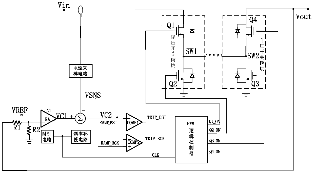
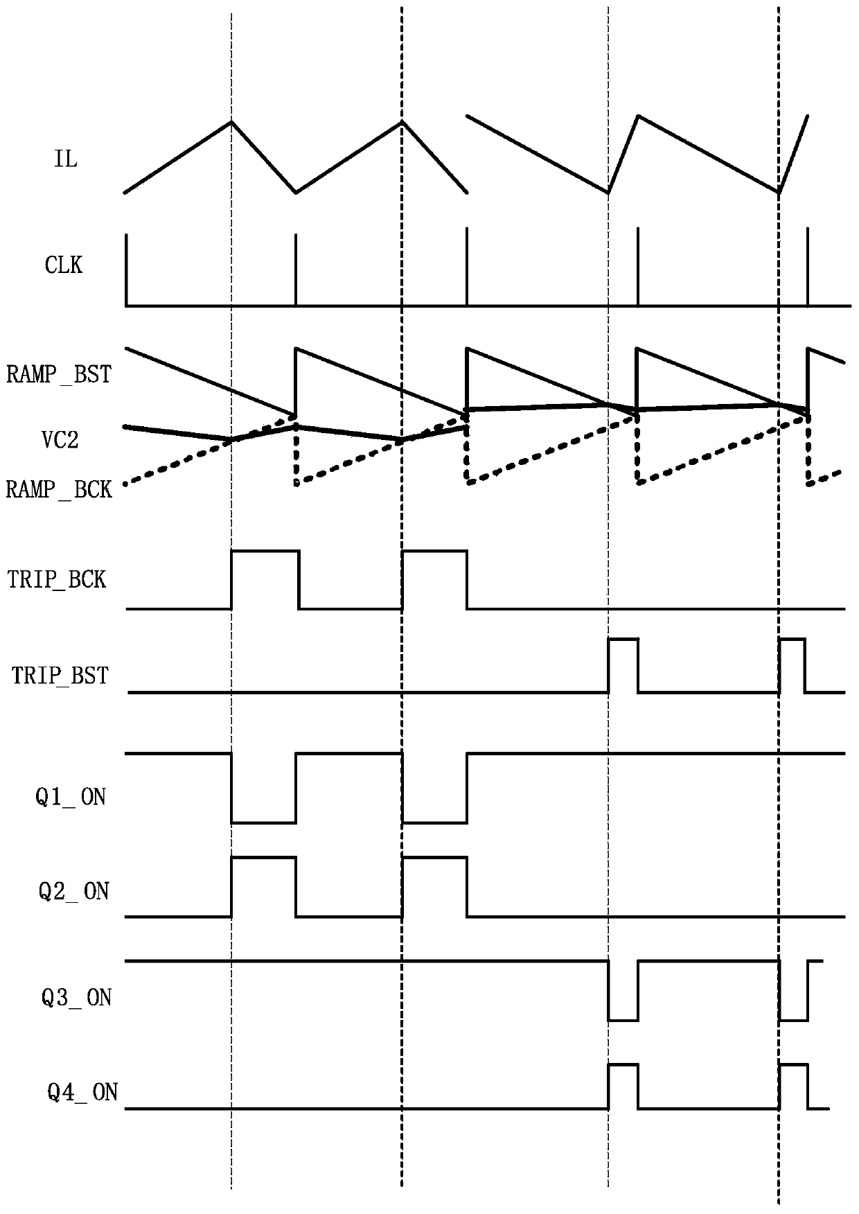
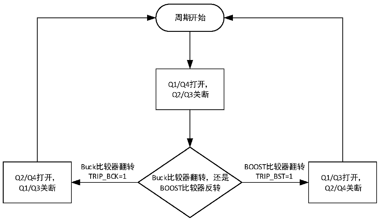
[0023] Such as Figure 1~3 As shown, a buck-boost DC-DC converter disclosed in the present invention includes a PWM logic controller, and power transistors Q1, Q2, Q3, and Q4 whose gates are connected to the PWM logic controller are connected to power transistors Q2, The inductance L between the drains of Q3, the comparators COMP1 and COMP2 whose output terminals are connected to the PWM logic controller, the subtractor whose output terminals are connected to the positive pole of the comparator COMP1 and the negative pole of the comparator COMP2, and the negative pole of the subtractor The connected current sampling circuit, the error amplifier A1 whose output terminal is connected to the positive pole of the subtractor, the slope compensation circuit whose two output terminals are respectively connected to the negative pole of the comparator COMP1 and the positive pole of the comparator COMP2, and the clock connected to the slope compensation circuit circuit; wherein, the oth...


PUM


Abstract

The invention discloses a buck-boost DC-DC converter and a control method. The smooth switching between a boost mode and a buck-boost mode of the DC-DC converter and the smooth switching between the buck-boost mode and buck mode of the DC-DC converter are achieved. The buck-boost DC-DC converter is simple to control; inductive current sampling signals are subtracted from error voltage signals; twopaths of slope compensation signals are combined to realize overturning control over a buck comparator and a boost comparator, and therefore, the converter works in different buck-boost modes, the switching of the converter from the boost mode to the buck-boost mode and the switching of the converter from the buck-boost mode to the buck mode are smoother, and current ripples and voltage ripples are smaller. Therefore, the buck-boost DC-DC converter and the control method are suitable for popularization and application.

Description

technical field [0001] The present invention relates to the technical field of power management, in particular to a buck-boost DC-DC converter and a control method. Background technique [0002] The application of buck-boost DC-DC converter is very flexible. When the output setting voltage is lower than the output voltage, the converter works in BUCK step-down mode, otherwise, when the output setting voltage is higher than the input voltage, the converter works in BOOST mode. Boost mode, when the output voltage is close to the input voltage, the converter works in BUCK-BOOST mode, the converter can automatically adjust the working mode according to the input / output voltage, seamlessly switch among the above three modes, and stabilize the output. [0003] The control of the existing buck-boost converter in the BUCK-BOOST mode is relatively complicated, and there is still room for optimization in the switching continuity among the three modes. Contents of the invention [0...

Claims


Application Information

Patent Timeline
IPC IPC(8): H02M3/158
CPCH02M3/1582
Inventor 濮正林
Owner SOUTHCHIP SEMICON TECH SHANGHAI CO LTD
Learn More