Video conference projection frame

A video conferencing and projection technology, which is applied in the direction of video conferencing systems, image reproducers using projection devices, color TVs, etc., can solve the problem of not being able to guarantee the projection direction of the screen and the projector, not being able to adjust the screen and the projector synchronously, and the angle of the screen and Position adjustment and other issues, to achieve the effect of easy storage and transportation, small footprint, free and flexible adjustment

Inactive Publication Date: 2020-06-09
常小兵
View PDF8 Cites 3 Cited by
  • Summary
  • Abstract
  • Description
  • Claims
  • Application Information

AI Technical Summary

Problems solved by technology

[0003] Existing projection stands are generally fixed on the wall. As the placement of the projector changes, its projection direction also changes. However, the fixed projection stand is not convenient for adjusting the angle and position of the screen, so it cannot Synchronous adjustment of the screen and the projector cannot guarantee that the projection direction of the screen and the projector is always perpendicular, so that the best projection effect cannot be displayed

Method used


Image

  • Video conference projection frame
  • Video conference projection frame
  • Video conference projection frame

Examples


Embodiment 1

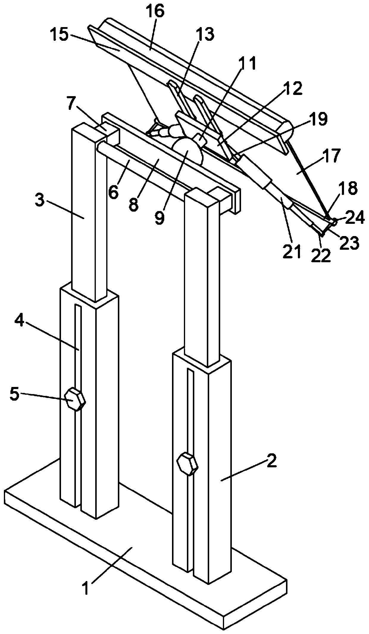
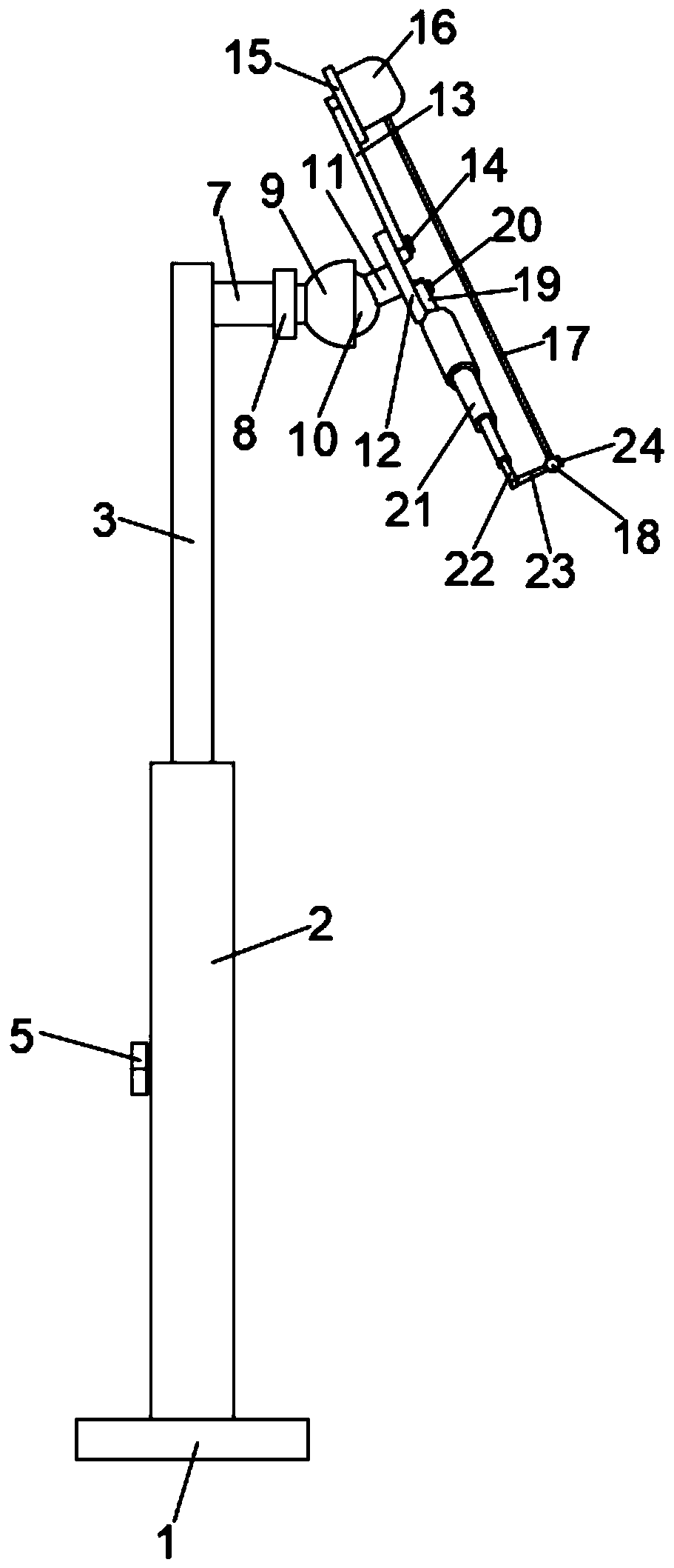
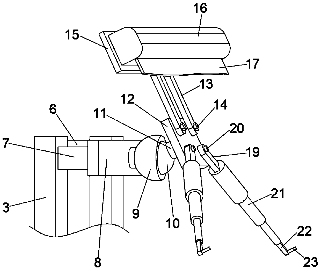
[0024] see Figure 1-3 , a video conference projection stand, including a base 1, a lifting assembly is installed on the base 1, a first mounting plate 8 is fixed on the upper end of the lifting assembly through a connecting plate 7, and the side wall of the first mounting plate 8 is located A ball sleeve 9 is fixed in the middle, and an adjusting ball 10 is movably embedded in the ball sleeve 9. A connecting column 11 is fixed on the adjusting ball 10, and a fixing plate 12 is installed at the end of the connecting column 11. The fixing plate 12 The upper end is equipped with a fixed frame 13 through a fixed bolt 14, and the lower end of the fixed plate 12 is connected with a movable frame 19 through a rotating shaft 20. The upper end of the fixed frame 13 is fixed with a second mounting plate 15, and the second mounting plate 15 is fixedly installed. There is a curtain box 16, and a curtain 17 is rolled up in the curtain box 16, and a counterweight pipe 18 is fixed at the lo...

Embodiment 2

[0034] A video conferencing projection stand, comprising a base 1, a lifting assembly is installed on the base 1, the upper end of the lifting assembly is fixed with a first mounting plate 8 through a connecting plate 7, and the middle part of the side wall of the first mounting plate 8 is A ball sleeve 9 is fixed, and an adjusting ball 10 is movably embedded in the ball sleeve 9. A connecting column 11 is fixed on the adjusting ball 10. A fixing plate 12 is installed at the end of the connecting column 11. The upper end of the fixing plate 12 A fixed frame 13 is installed by a fixed bolt 14, and the lower end of the fixed plate 12 is connected with a movable frame 19 through a rotating shaft 20. The upper end of the fixed frame 13 is fixed with a second mounting plate 15, and the second mounting plate 15 is fixedly installed with a Curtain box 16, the curtain box 16 is rewound with a curtain 17, the lower end of the curtain 17 is fixed with a counterweight tube 18; the lower e...


PUM


Abstract

The invention discloses a video conference projection frame which comprises a base. A lifting assembly is installed on the base. A ball sleeve is fixed to the upper end of the lifting assembly. An adjusting ball is movably embedded in the ball sleeve. A connecting column is fixed to the adjusting ball. A fixed plate is installed at the tail end of the connecting column. A fixed frame and a movableframe are installed on the fixed plate. A second installation plate is fixed to the tail end of the fixed frame, a curtain box is fixedly installed on the second installation plate, and a multi-stageelastic telescopic rod is fixed to the lower tail end of the movable frame. The video conference projection frame is simple in structure and small in occupied space. The lifting assembly, the adjusting ball and the multi-stage elastic telescopic rod are respectively arranged, so that the height, any angle and flatness of the curtain are adjusted, the adjustment is free and flexible, the operationis simple and rapid, the use requirements of different places can be met, the frame can be folded and stored after being used, the storage, carrying and transportation are convenient, the structure is stable and reliable, and the projection effect is good.

Description

technical field [0001] The invention relates to the technical field of video conference auxiliary equipment, in particular to a video conference projection stand. Background technique [0002] The current video conferencing often uses projectors. The projectors are usually placed on the desktop or fixed on the indoor ceiling. In order to obtain better projection effects, the projection screen and the projector are generally used together. The projection screen is placed on the projection stand , and then point the projector to the screen to project. [0003] Existing projection stands are generally fixed on the wall. As the placement of the projector changes, its projection direction also changes. However, the fixed projection stand is not convenient for adjusting the angle and position of the screen, so it cannot Synchronous adjustment of the screen and the projector cannot ensure that the projection direction of the screen and the projector is always perpendicular, so tha...

Claims


Application Information

Patent Timeline
Patent Type & Authority Applications(China)
IPC IPC(8): H04N7/15H04N9/31
CPCH04N7/15H04N9/3141
Inventor 常小兵
Owner 常小兵
Why Eureka
Try Eureka