[0026] The technical solutions in the embodiments of the present invention will be clearly and completely described below in conjunction with the accompanying drawings in the embodiments of the present invention. Obviously, the described embodiments are only some of the embodiments of the present invention, not all of them. Based on The embodiments of the present invention and all other embodiments obtained by persons of ordinary skill in the art without making creative efforts belong to the protection scope of the present invention.
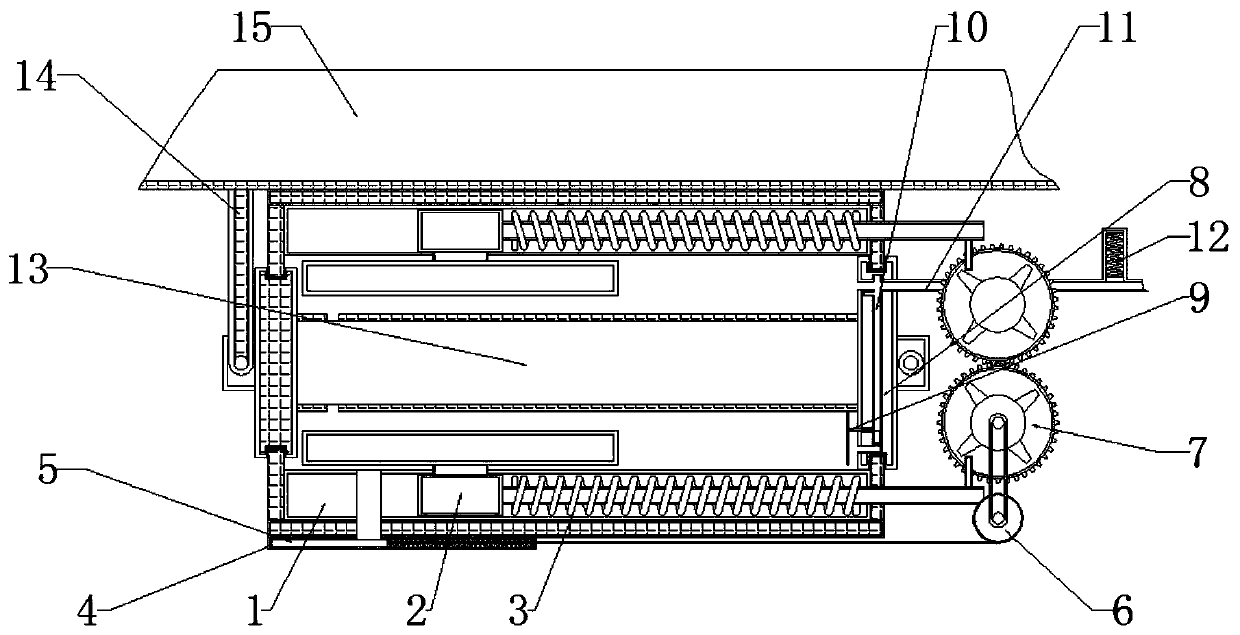
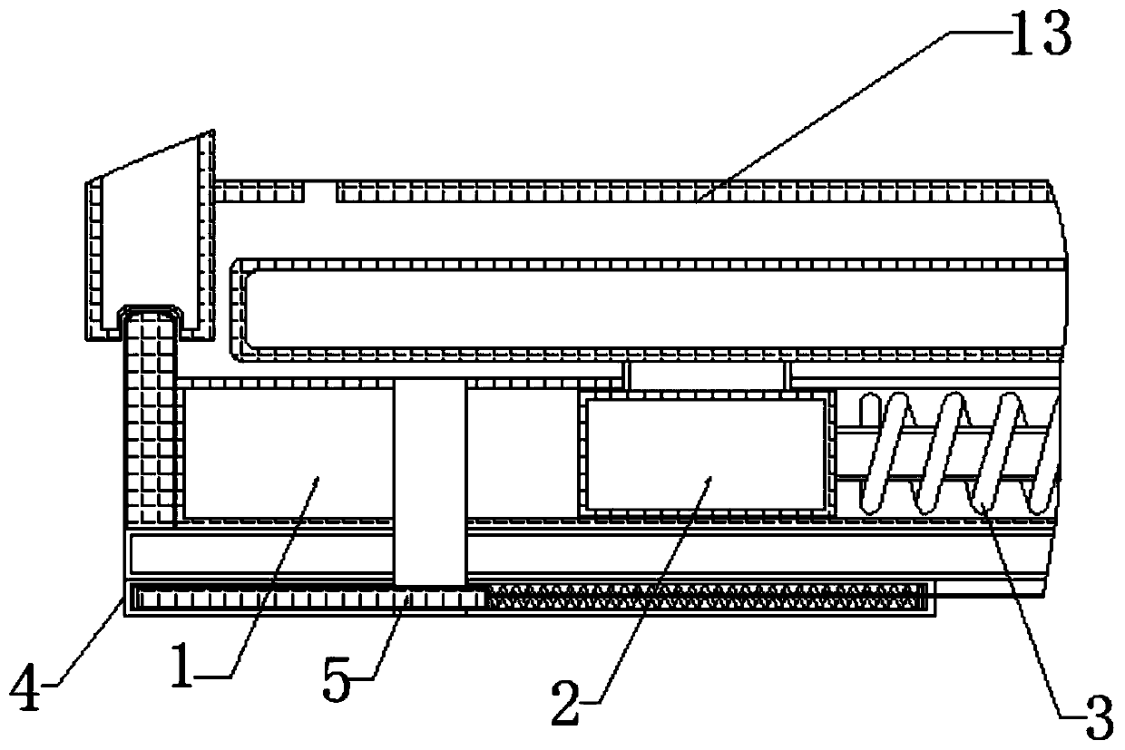
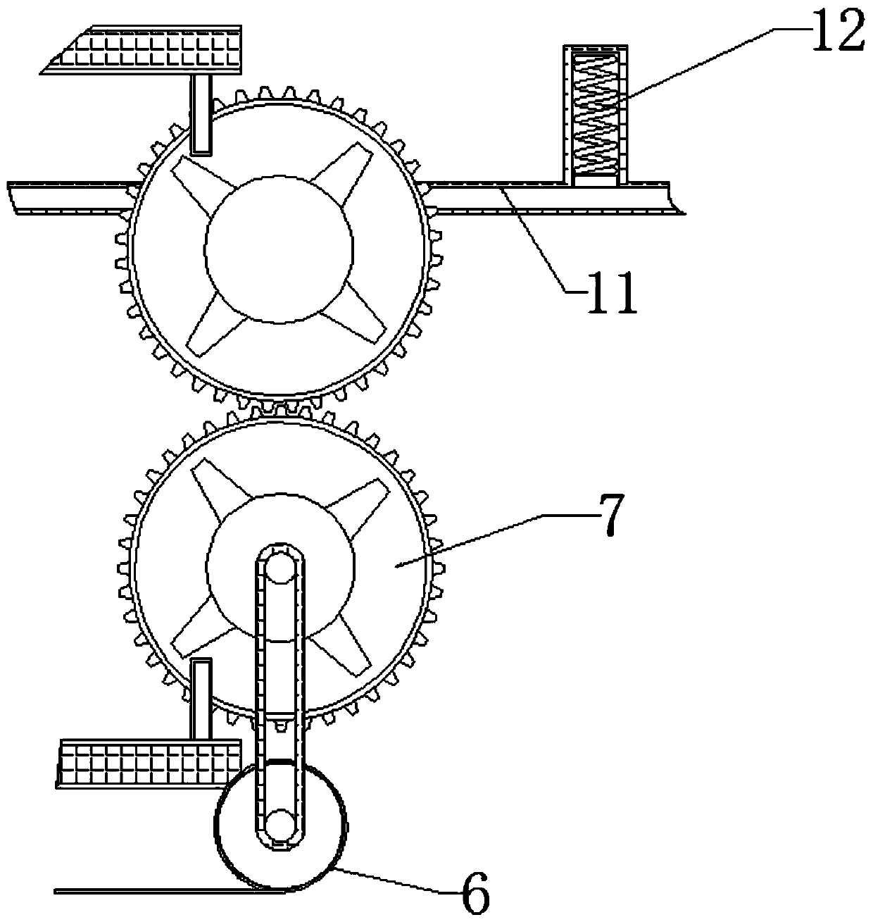
[0027] see Figure 1-5 , an intelligent automatic control device for cleaning hydraulic support rods, including a closed plate 1, a sewage pipe is movably connected to the inside of the closed plate 1 below, the movable slider 2 is designed with a decontamination brush, and the right side of the movable slider 2 is fixedly connected There is a fixed rod, the inner movable connection of the closed disk 1 is connected with the movable slider 2, the inner movable connection of the closed disk 1 is connected with the return spring 3, and the hydraulic rod 3 and the support base 8 are provided with grooves to ensure that the closed disk 1 is stuck and formed. The cavity, the bottom of the closed disk 1 is movably connected with a sewage discharge track 4, the inside of the sewage discharge rail 4 is movably connected with a pollution control slider 5, and the right side of the closed disk 1 is movably connected with a transmission wheel 6, the transmission wheel 6 and the cleaning wheel 7 and The pollution control sliders 5 are all connected by belt transmission. The cleaning wheel 7 is movably connected above the valve of the transmission wheel 6. The cleaning wheel 7 is designed with four large teeth to ensure the cleaning of the cleaning hydraulic rod 14. The left side of the cleaning wheel 7 A support base 8 is movably connected, and the inside of the support base 8 is movably connected with a card slot, and the left side of the support base 8 is movably connected with a pressure plate 9, and the inside of the support base 8 is movably connected with a water control track 10, and the inside of the water control track 10 A floating slider is movably connected to ensure that the water inlet of the water inlet pipe 11 is controlled. The upper part of the support base 8 is movably connected with a water inlet pipe 11. The water inlet pipe 11 starts to fill the closed space formed by the two closed disks 1 with water. When the water is filled When the amount of water reaches a certain level, the pressure plate 9 below moves to the right under the pressure of the water, and at the same time drives the card slot on the left side of the water control track 10 to move to the right, and as the water level rises, it drives the floating movement inside the water control track 10. The slider moves upward, and when the floating slider floats up to the nozzle position of the water inlet pipe 11, the water inlet pipe 11 stops filling the cavity formed by the closed disk 1, and a control valve 12 is movably connected above the water inlet pipe 11, and the control valve The inside of 12 is movably connected with control slide block and control spring, and the left side of support base 8 is movably connected with hydraulic rod 13, and the left end of hydraulic rod 13 is movably connected with movable rod 14, and the top of movable rod 14 is movably connected with drag bucket 15.
[0028] Working principle: When the outside of the hydraulic rod 13 is covered with dust, by resetting the tow bucket 15, the closed disk 1 fixedly connected under the tow bucket 15 and the closed disk 1 below the hydraulic rod 13 snap into the recesses at both ends of the hydraulic rod 13 In the tank, the water inlet pipe 11 starts to fill the closed space formed by the two closed discs 1 with water. When the amount of water filled reaches a certain level, the pressure plate 9 below moves to the right under the pressure of the water, and at the same time drives the water control track The slot on the left side of 10 moves to the right, and as the water level rises, it drives the floating slider inside the water control track 10 to move upward. The cavity formed by the closed disk 1 is filled with water, and the clamping groove clamps and fixes the floating slider. When the water inside the water inlet pipe 11 cannot enter the inside of the closed disk 1, as the water pressure of the water inlet pipe 11 rises, the push control The control slider inside the valve 12 moves upwards and compresses the control spring at the same time to control the cleaning wheel 7 to start rotating. The cleaning wheel 7 adopts four large teeth. When the large teeth touch the fixed rod fixedly connected with the movable slider , to drive the movable slider 2 to move to the right. When the large tooth is separated from the fixed rod, the movable slider 2 is reset under the elastic force of the movable spring. At the same time, a decontamination brush is movably connected under the movable slider 2. The movement of the hydraulic rod 13 brushes away the dust on the outside of the hydraulic rod 13, and with the rotation of the lower cleaning wheel 7, the lower cleaning wheel 7 and the transmission wheel 6 are connected through a belt transmission, which further drives the transmission wheel 6 to rotate, and at the same time the transmission wheel 6 A transmission belt is movably connected with the pollution control slider 5, which further drives the pollution control slider 5 to move to the right. discharge, and because the sewage is discharged, the pressure plate 9 loses the water pressure and resets, the floating slider slides down the water inside the water inlet pipe 11 and enters the closed disk 1, the control valve 12 loses the water pressure and resets, and the cleaning wheel 7 stops rotating. After the cleaning is completed, the water inlet pipe 11 is controlled to be closed.
[0029] To sum up, the intelligent automatic control device for cleaning the hydraulic support rod starts to fill the closed space formed by the two closed plates 1 with water through the water inlet pipe 11, and the pressure plate 9 below moves to the right under the pressure of the water. At the same time, it drives the draw-in groove on the left side of the water control track 10 to move to the right, drives the floating slider inside the water control track 10 to move upward, and the water inlet pipe 11 stops filling the cavity formed by the closed disc 1, and the draw-in groove will float and slide The block is stuck and fixed, and as the water pressure of the water inlet pipe 11 rises, the control slider inside the control valve 12 is pushed to move upwards and the control spring is compressed at the same time, the control cleaning wheel 7 starts to rotate, driving the movable slider 2 to move to the right, and the movable slider The block 2 resets under the elastic force of the movable spring, and at the same time, a decontamination brush is movably connected to the bottom of the movable slider 2, and the dust etc. on the outside of the hydraulic rod 13 are brushed away by the movement of the decontamination brush, thereby achieving the purpose of removing the hydraulic rod 13 The effect of external cleaning improves work efficiency.
[0030] This intelligent automatic control device for cleaning the hydraulic support rod, when the outer side of the hydraulic rod 13 is covered with dust, by resetting the tow bucket 15, the closed disk 1 fixedly connected under the tow bucket 15 and the closed disk 1 below the hydraulic rod 13 Snap into the grooves at both ends of the hydraulic rod 13, thereby achieving the effect of forming a cavity, ensuring that the water entering the water inlet pipe 11 can clean the hydraulic rod 13.
[0031]The intelligent automatic control device for cleaning the hydraulic support rod further drives the transmission wheel 6 to rotate through the belt transmission connection between the cleaning wheel 7 and the transmission wheel 6, and at the same time, a transmission belt is movably connected between the transmission wheel 6 and the pollution control slider 5 , to further drive the pollution control slider 5 to move to the right, when the pollution control slider 5 moves to the right past the position of the sewage discharge pipe mouth, the cleaned sewage is discharged through the sewage discharge pipe, thereby achieving the effect of sewage discharge after the cleaning is completed, Guaranteed that the sewage is discharged rapidly and the hydraulic rod 13 is corroded.
[0032] Although the embodiments of the present invention have been shown and described, those skilled in the art can understand that various changes, modifications and substitutions can be made to these embodiments without departing from the principle and spirit of the present invention. and modifications, the scope of the invention is defined by the appended claims and their equivalents.