A portable medical puncher
A puncher, portable technology, applied in the direction of punching tools, chemical instruments and methods, forming tools, etc., can solve the problems of inapplicability, achieve the effects of convenient operation, improved punching success rate, and low cost
- Summary
- Abstract
- Description
- Claims
- Application Information
AI Technical Summary
Problems solved by technology
Method used
Image
Examples
Embodiment 1
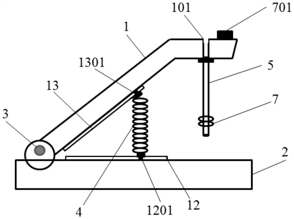
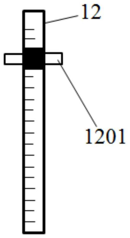
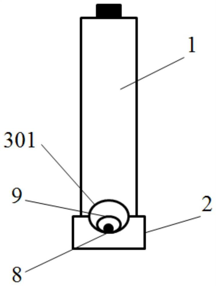
[0059] The structure of the portable medical puncher of the present embodiment is as Figure 1-5 As shown, the puncher includes a base 2 with a groove 201 and a handle 1 with a punching head 5, the groove 201 is located in the middle of the upper surface of the base 2, and runs through the front end and the end of the base 2; The groove 201 is a semicircular surface groove, and the inside of the groove 201 is used to place the medical catheter 9 that needs to be punched, which plays the role of positioning the catheter 9, and prevents the punching head 5 from pressing the catheter 9 when the hole is punched. out of shape.
[0060] The end of the base 2 is movably connected with the end of the handle 1 through the pin shaft 3, so that the handle 1 can rotate up and down with the pin shaft 3 as the axis. When the base 2 is fixed and the handle 1 turns upwards, the handle 1 drives the punching head 5 away from the conduit 9 at the groove 201, and when the handle 1 turns downward...
Embodiment 2
[0074] The structure of the portable medical puncher of the present embodiment is as Figure 6-7 As shown, in order to avoid the trouble of disassembling and assembling the punching head 5 each time, improve the punching efficiency, and strive for precious medical time, the present embodiment installs a circular guide rail 11, and the punching head 5 is detachably fixed on the circular guide rail by a buckle. 11 lower surface, and can move with the ring guide rail 11. Ring guide rail 11 is located at the place ahead of handle 1 front end, and a punching head 5 at the end of ring guide rail 11 is the punching head used for punching, and all the other punching heads are positioned at the place ahead of the punching head used.
[0075] When in use, the punching head on one side of the circular guide rail 11 moves from front to rear in turn, and moves to the punching head at the end of the circular guide rail 11 to punch holes. After punching, the punching head continues to move a...
Embodiment 3
[0082] The using method of the portable medical puncher of embodiment 1 comprises the following steps:
[0083] (1) Choose a steel wire galvanized spring with a free height of 6mm and install it between the handle and the base; the hole to be punched is 0.3mm in diameter, choose a punching head with the corresponding diameter, and install it at the front of the handle;
[0084] (2) Disinfect the punch as a whole;
[0085] (3) Put the medical catheter into the groove, and adjust the position of the catheter to be punched directly below the punching head;
[0086] (4) Insert the sterilized magnetic rod into the catheter, fix the catheter, turn on the magnetic field of the electromagnetic coil, and put the sterilized magnetic piece into the punching head;
[0087] (5) Adjust the position of the spring on the first slide rail and the second slide rail, and fix the top and bottom of the spring;
[0088] (6) Press down on the handle, when the bottom of the punching head touches th...
PUM
| Property | Measurement | Unit |
|---|---|---|
| pore size | aaaaa | aaaaa |
| diameter | aaaaa | aaaaa |
Abstract
Description
Claims
Application Information
 - R&D
- Intellectual Property
- Life Sciences
- Materials
- Tech Scout
- Unparalleled Data Quality
- Higher Quality Content
- 60% Fewer Hallucinations
Browse by: Latest US Patents, China's latest patents, Technical Efficacy Thesaurus, Application Domain, Technology Topic, Popular Technical Reports.
© 2025 PatSnap. All rights reserved.Legal|Privacy policy|Modern Slavery Act Transparency Statement|Sitemap|About US| Contact US: help@patsnap.com


