Stress relief stamping die, stress relief stamping method and metal plate stamping part

A stamping die and stress relief technology, which is applied in the field of metal plate stamping parts and stress relief stamping dies, can solve problems such as difficulty in ensuring flatness, plastic deformation of metal plates, and affecting equipment use, and achieve stable operation and stable flatness Effect

Inactive Publication Date: 2020-06-12
沪华五金电子(吴江)有限公司
View PDF0 Cites 1 Cited by
  • Summary
  • Abstract
  • Description
  • Claims
  • Application Information

AI Technical Summary

Problems solved by technology

[0004] However, the metal plate will undergo plastic deformation during stamping and forming, and internal stress will be generated inside the material. If the internal stress is not eliminated or restricted, the metal plate will warp when the internal stress is released, and it is difficult to ensure its overall flatness
Therefore, even if the flatness of the stamped metal plate stamping parts is adjusted by the orthopedic device, the internal stress caused by the deformation of the material still exists, and the metal plate may still release the internal stress and warp during use, thus affecting Equipment
In some occasions, especially in the electronic field, such as in the chassis, the flatness of the stamped metal parts is highly required. If the flatness of the stamped metal parts cannot be guaranteed, once the metal plate warps and touches the electronic components , it is easy to burn out electronic components and make the equipment scrapped

Method used


Image

  • Stress relief stamping die, stress relief stamping method and metal plate stamping part
  • Stress relief stamping die, stress relief stamping method and metal plate stamping part
  • Stress relief stamping die, stress relief stamping method and metal plate stamping part

Examples


Embodiment Construction

[0030] The technical solution of the present invention will be further described in non-limiting detail below in conjunction with preferred embodiments and the accompanying drawings.

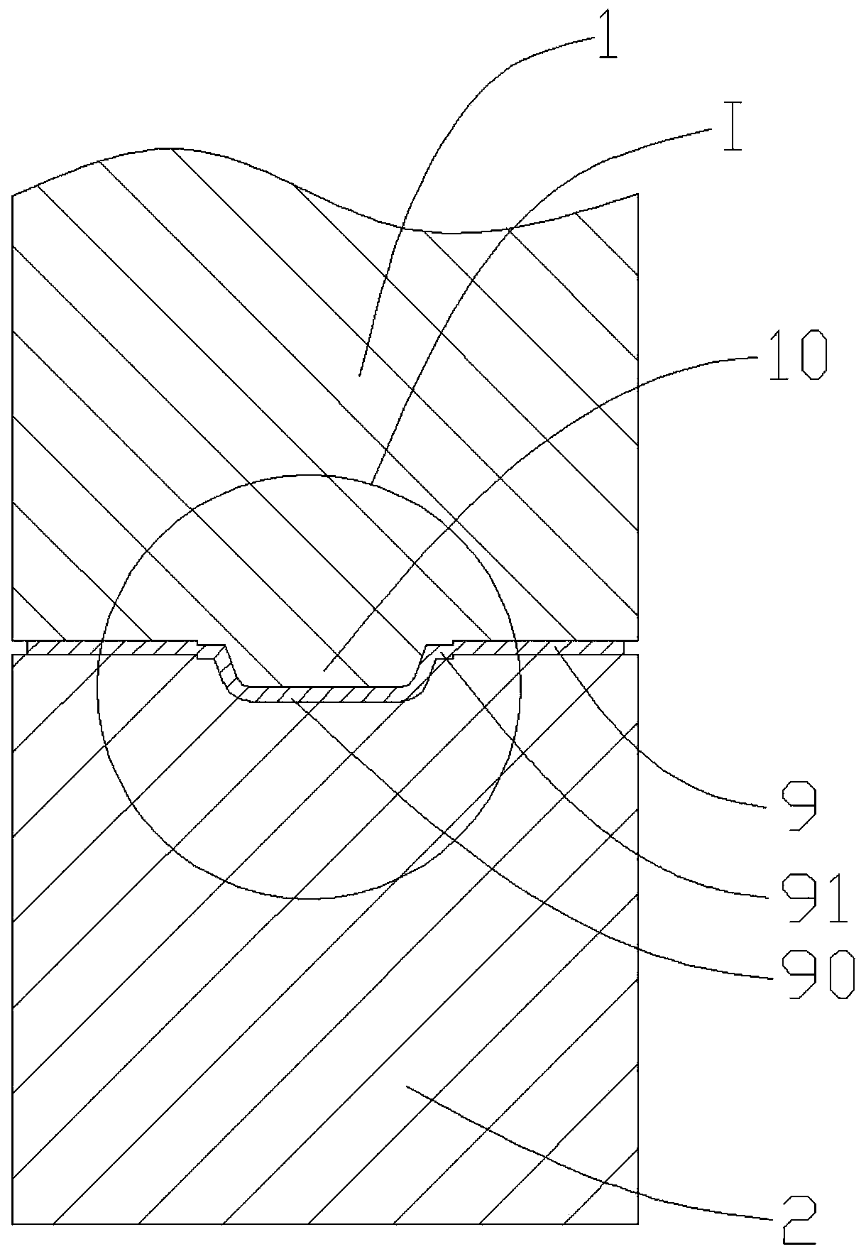
[0031] Such as image 3 As shown, a stress relief stamping die corresponding to a preferred embodiment of the present invention includes a male mold 1 and a female mold 2. The male mold 1 is fixed on the upper mold of the press, and the female mold 2 is fixed on the press On the base of the lower mold.

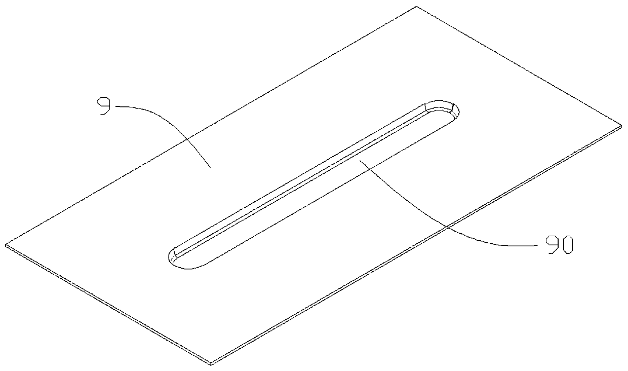
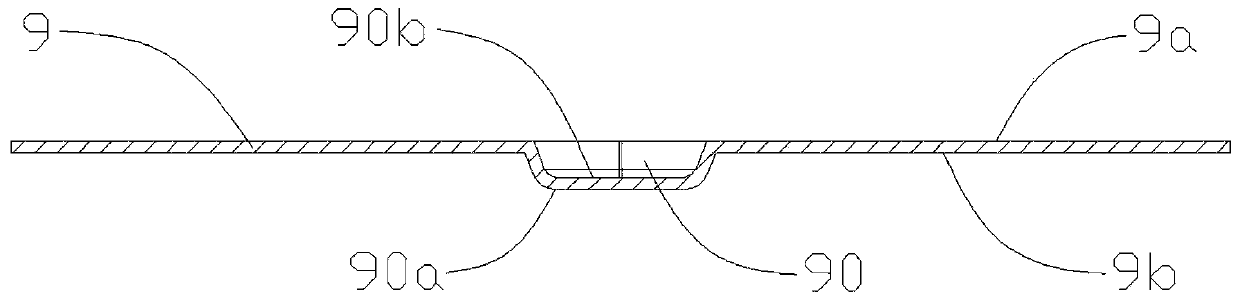
[0032] Further reference Figure 4 with Figure 5 , The male mold 1 includes an indenter 10 protruding toward the female mold 2 and a step 11 surrounding the outer periphery of the indenter 10. The indenter 10 matches the inner concave surface 90b of the sheet metal stamping part, and is used to extrude the sheet metal during punching to form the inner concave surface 90b of the sheet metal stamping part.

[0033] Such as Image 6 with Figure 7 As shown, the concave mold 2 includes a molding cavity 2...


PUM

PropertyMeasurementUnit
thicknessaaaaaaaaaa
widthaaaaaaaaaa

Abstract

The invention discloses a stress relief stamping die, a stress relief stamping method and a metal plate stamping part. The stress relief stamping die is used for stamping a convex hull on a plate bodyof a metal plate and comprises a male die and a female die, the male die comprises a pressing head protruding towards the female die, the female die comprises a forming cavity corresponding to the pressing head, the forming cavity and the pressing head are matched to form the convex hull, the male die comprises a step surrounding the periphery of the pressing head, and the female die comprises astep groove surrounding the periphery of the forming cavity. The step surrounding the periphery of the pressing head is arranged on the male die, and the step groove surrounding the periphery of the forming cavity is arranged on the female die, so that during stamping, a circle of externally convex step part can be formed on the periphery of the convex hull of the metal plate stamping part, so that the internal stress between the convex hull and the plate body is sheared, the deformation of the plate body caused by relief of the internal stress is effectively limited, the stability of the flatness is guaranteed, and the stable operation of equipment is facilitated.

Description

Technical field [0001] The invention relates to the technical field of stamping, and in particular to a stress-relief stamping die, a stress-relief stamping method and a metal plate stamping part. Background technique [0002] Stamping is a very common processing technology. It mainly relies on presses and molds to apply external force to plates, strips, pipes and profiles to cause plastic deformation or separation, so as to obtain workpieces (stamping parts) of the required shape and size. [0003] Because the metal sheet is thin and its rigidity is poor, it is easy to deform. Therefore, in the application, a number of elongated convex hulls are often stamped and formed on the metal sheet to improve its overall mechanical strength, such as figure 1 with figure 2 Shown. figure 1 with figure 2 The metal plate stamping shown includes a plate body 9 and a convex hull 90 protruding from the plate body 9. Specifically, the plate body 9 includes an upper surface 9a and a lower surface 9...

Claims


Application Information

Patent Timeline
Patent Type & Authority Applications(China)
IPC IPC(8): B21D37/10B21D22/02
CPCB21D22/02B21D37/10
Inventor 陈志刚
Owner 沪华五金电子(吴江)有限公司
Why Eureka
Try Eureka