Safe heat-insulated welding clamp

An electric welding tongs, safe technology, applied in the field of electric welding tongs, can solve the problems of fast heating of the lower conductor, large contact area, heating of the handle, etc., achieve good ventilation effect, slow heat transfer speed, and reduce the contact area.

Pending Publication Date: 2020-06-12
马乐亮
View PDF0 Cites 1 Cited by
  • Summary
  • Abstract
  • Description
  • Claims
  • Application Information

AI Technical Summary

Problems solved by technology

[0003] The electric welding tongs of the prior art have the following disadvantages: 1. The cable of the traditional electric welding tongs is connected to the lower conductor, because the conductor is too long to cause the jaws to heat up, resulting in premature heating of the handle; 2. The lower part of the existing electric welding tongs is conductive. The body is smoothly connected with the main conductor on the upper end of the welding tongs, the contact area is large, and the lower conductor heats up quickly when used; 3. The traditional cable is fixed on the welding tongs, and the handle shell needs to be removed when the cable is installed and repaired, which is inconvenient to use; , we propose a safe heat-insulated welding tongs

Method used


Image

  • Safe heat-insulated welding clamp
  • Safe heat-insulated welding clamp
  • Safe heat-insulated welding clamp

Examples


Embodiment Construction

[0021] In order to make the purpose, technical solutions and advantages of the present invention clearer, the present invention will be further described in detail below in conjunction with the accompanying drawings. Obviously, the described embodiments are only some of the embodiments of the present invention, rather than all of them. Based on the embodiments of the present invention, all other embodiments obtained by persons of ordinary skill in the art without making creative efforts belong to the protection scope of the present invention.

[0022] The following will combine Figure 1 to Figure 4 A safety heat-insulating electric welding tongs according to an embodiment of the present invention will be described in detail.

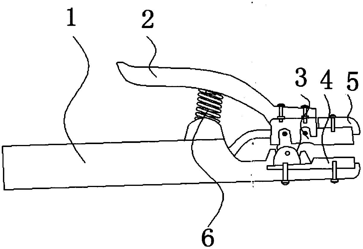
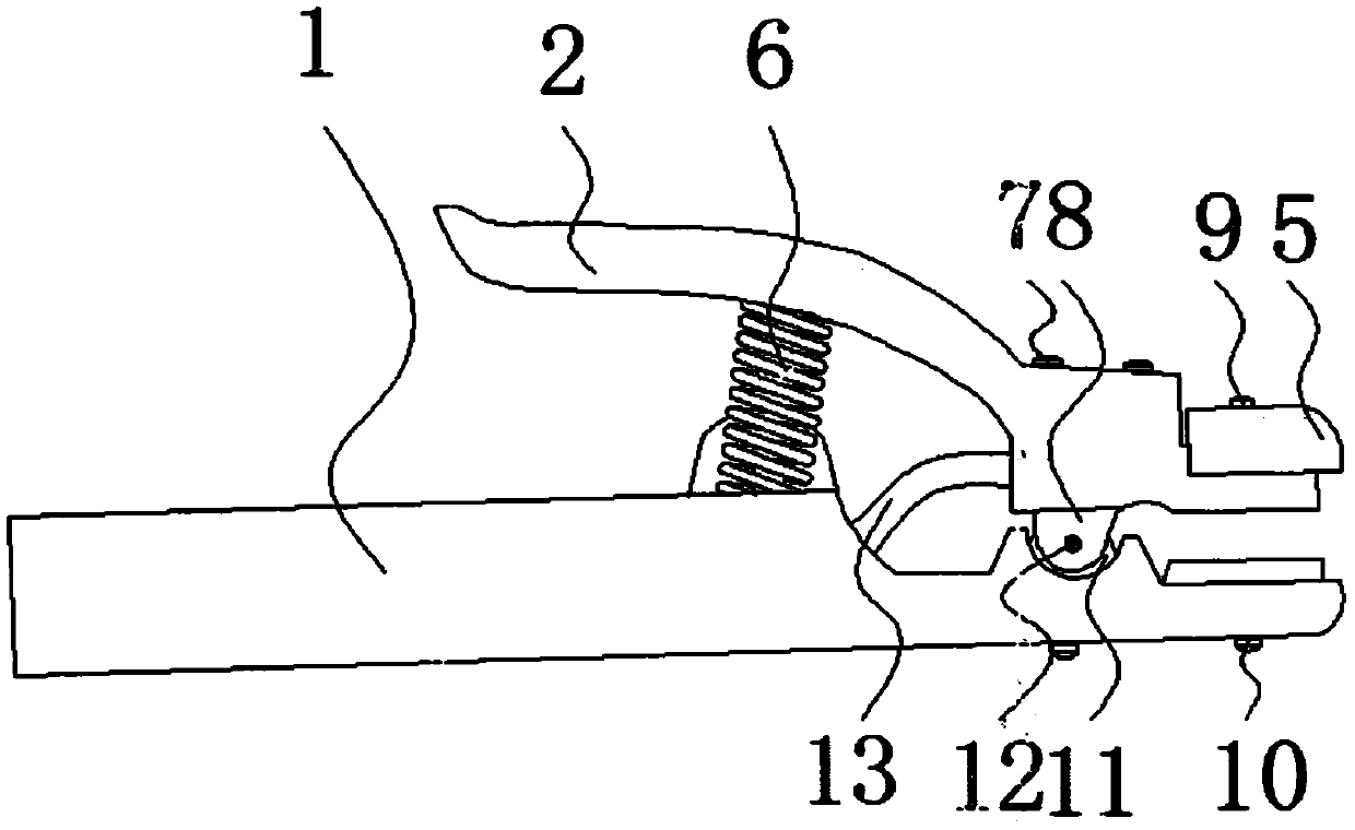
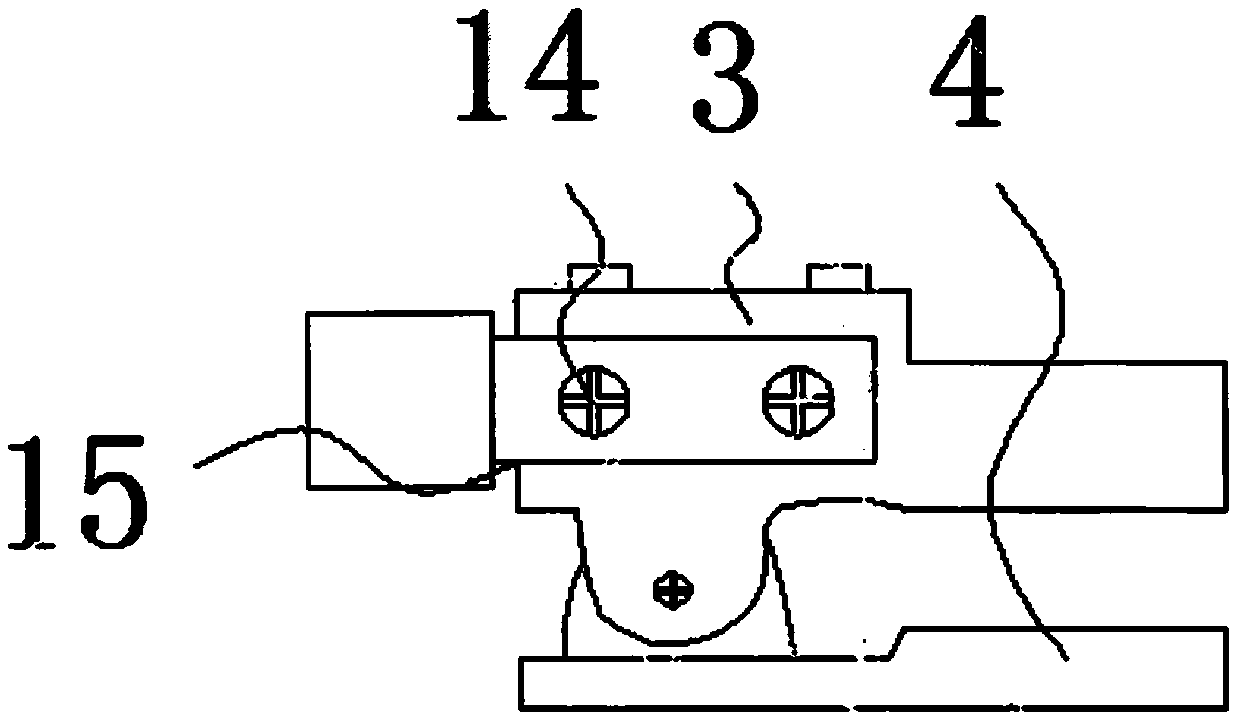
[0023] refer to Figure 1 to Figure 4 As shown, a safety heat-insulating electric welding tongs provided by the embodiment of the present invention includes a handle 1, an upper pressure handle 2, an upper main conductor 3, a lower conductor 4, an uppe...


PUM


Abstract

The invention discloses a safe heat-insulated welding clamp, and belongs to the technical field of welding clamps. The safe heat-insulated welding clamp comprises a handle, an upper pressure handle, an upper main electric conductor, a lower branch electric conductor, an upper protective cover and a spring, wherein the lower branch electric conductor is installed at the front end of the handle, thetail portion of the lower branch electric conductor is in interference fitting with a protruding fixing point b, the two sides of the tail portion of the upper main electric conductor are in interference fitting with protruding fixing points a, and the protruding fixing points a are connected with the protruding fixing point b through fixing plugs. A wire inlet is formed in the tail portion of the upper main electric conductor, the upper main electric conductor is in clearance fit with a cable through a groove screw, and the cable penetrates through the handle and is in clearance fit with theinterior of the upper main electric conductor. The cable is connected with the upper main electric conductor, so that the generated heat is concentrated upon the upper portion of the welding clamp, and the handle is prevented from emitting heat too early; the surface, making contact with the lower branch electric conductor, of the handle is small, the handle is indirectly connected with the uppermain electric conductor to be away from a heating source, and the anti-scald effect is obvious; the cable penetrates through the handle to be installed in the upper main electric conductor, and convenience is brought to disassembly.

Description

technical field [0001] The invention relates to the technical field of electric welding tongs, in particular to a safety heat-insulating electric welding tongs. Background technique [0002] Welding pliers, tools for electric welding, have two handles. Shaped like pliers, the function is to hold the welding rod and conduct the welding current during welding. It is used in conjunction with the arc welding machine. During manual arc welding, it is used to hold and manipulate the electrode and ensure the electrical connection with the electrode. [0003] The electric welding tongs of the prior art have the following disadvantages: 1. The cable of the traditional electric welding tongs is connected to the lower conductor, because the conductor is too long to cause the jaws to heat up, resulting in premature heating of the handle; 2. The lower part of the existing electric welding tongs is conductive The body is connected smoothly with the main conductor on the upper end of the...

Claims


Application Information

Patent Timeline
Patent Type & Authority Applications(China)
IPC IPC(8): B23K9/28B23K9/32
CPCB23K9/28B23K9/32
Inventor 马乐亮
Owner 马乐亮
Why Eureka
Try Eureka