A drone mounting system for direct seeding of rice
A mounting system and unmanned aerial vehicle technology, applied to aircraft parts, launching devices, transportation and packaging, etc., to achieve the effect of strong pushing force, consistent power, and convenient feeding
- Summary
- Abstract
- Description
- Claims
- Application Information
AI Technical Summary
Problems solved by technology
Method used
Image
Examples
Embodiment 1
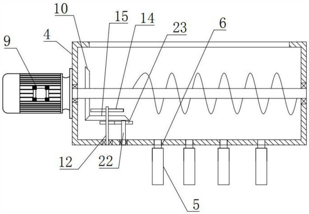
[0045] Such as Figure 1-2 and Figure 5-8 Shown, a kind of unmanned aerial vehicle mounting system of live rice, comprises accommodation box 3, power box 4 and sorting pipe 5, and described accommodation box 3 is the structure of top and bottom opening, and described accommodation box 3 is arranged on no The lower part of the man-machine 1, the power box 4 is arranged at the bottom of the storage box 3 and communicates with the opening at the bottom of the storage box 3, and the outer bottom of the power box 4 is evenly provided with a plurality of connected flow nozzles 6, the seeding pipes 5 have many and one end thereof is respectively connected with a plurality of flow nozzles 6 one by one, the other end of the seeding pipes 5 is fixed by a cross bar 7, and the cross bar 7 is connected to the The frame 8 of the unmanned aerial vehicle 1 is connected;
[0046] Such as Figure 5 As shown, the drive motor for pushing materials is arranged outside the power box, the output...
Embodiment 2
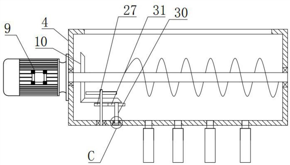
[0054] Such as image 3 and Figure 4 As shown, the difference between this embodiment and Embodiment 1 is that the connecting shaft 12 is provided with a fifth transmission gear 27, and the inner bottom of the power box 4 is sequentially provided with connecting connecting holes 28 from top to bottom. and a vibrating hole 29, the vibrating hole 29 has a frustum-shaped structure, the connecting hole 28 is rotated with a bearing, the vibrating mechanism includes a rotating shaft 30, and the rotating shaft 30 is sleeved at the inner ring of the bearing. A vibrating table 43 and a sixth transmission gear 31 meshing with the fifth transmission gear 27 are arranged on the rotating shaft 30 , the vibrating table 43 has a frustum-shaped structure and is arranged in the vibrating hole 29 .
[0055] Wherein, the vibration hole 29 is arranged at the middle position of the inner bottom of the power box 4, so that the imbalance problem caused by its gravity can be avoided.
[0056] In t...
Embodiment 3
[0058] Such as Figure 5-13 As shown, the difference between this embodiment and the other two embodiments is that each of the split nozzles 6 is rotatably connected with a first rotating plate 11, and the center of the first rotating plate 11 is provided with a connecting shaft 12, so The first rotating plate 11 is also provided with a first blanking hole 13, and the connecting shaft 12 close to the first bevel gear 10 is sequentially provided with a first transmission gear 14 and a meshing gear with the first bevel gear 10 from top to bottom. The second bevel gear 15, the other connecting shafts 12 are provided with a second transmission gear 16, the second transmission gear 16 close to the first transmission gear 14 is meshed with the first transmission gear 14, and the second transmission gear 16 is mutually in turn Engage;
[0059] Such as Figure 9 and 10 As shown, the first helical spring piece 17 is arranged inside the seeding tube 5, the upper end of the first heli...
PUM
 Abstract
Description
Claims
Application Information
 - R&D
- Intellectual Property
- Life Sciences
- Materials
- Tech Scout
- Unparalleled Data Quality
- Higher Quality Content
- 60% Fewer Hallucinations
Browse by: Latest US Patents, China's latest patents, Technical Efficacy Thesaurus, Application Domain, Technology Topic, Popular Technical Reports.
© 2025 PatSnap. All rights reserved.Legal|Privacy policy|Modern Slavery Act Transparency Statement|Sitemap|About US| Contact US: help@patsnap.com


