
Seed drying device

A drying device and seed technology, applied in drying, drying machine, drying gas arrangement, etc., can solve the problems that seeds cannot be heated and dried, uneven drying, etc., to save manpower, improve flexibility, and evenly feed Effect

Inactive Publication Date: 2017-08-18
安徽菲扬新材料有限公司
View PDF8 Cites 10 Cited by
  • Summary
  • Abstract
  • Description
  • Claims
  • Application Information

AI Technical Summary

Problems solved by technology

However, the heat of the drying operation of this utility model comes out from the stirring rod, and because there is a dead angle in the stirring, the seeds that cannot be stirred cannot be heated and dried, resulting in uneven drying

Method used


Image

  • Seed drying device
  • Seed drying device
  • Seed drying device

Examples


Embodiment 1

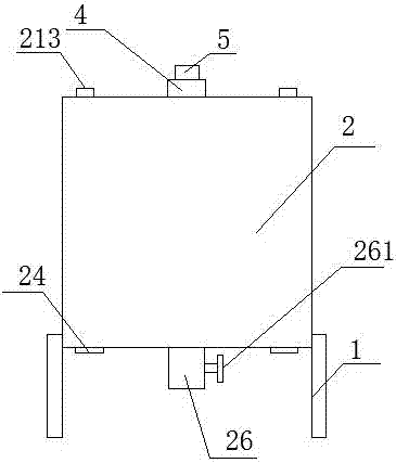
[0033] As shown in Figure 1, it is a schematic structural view of a seed drying device in Embodiment 1, including a frame 1 and a drying barrel 2 arranged on the frame 1, and the top of the drying barrel 2 is provided with at least two feeders. mouth 211, the bottom of the drying barrel 2 is provided with a discharge pipe 26, the discharge pipe 26 is provided with a valve 261, the drying barrel 2 includes an outer barrel body 21 and an inner barrel body 22, and the top of the inner barrel body 22 is connected to the top of the outer barrel body 21 , the inner barrel body 22 and the outer barrel body 21 have the same axis line, and the discharge pipe 26 runs through the inner barrel body 22 and the outer barrel body 21 .

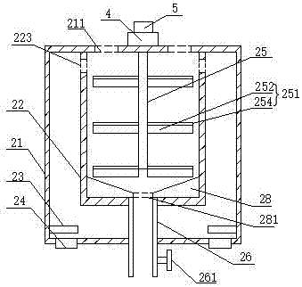
[0034] Such as figure 2 Shown is a cross-sectional view of a drying barrel of a seed drying device in Embodiment 1. A heating pipe 221 is horizontally provided at the bottom of the side wall of the outer barrel body 21. The heating pipe 221 can be connected t...

Embodiment 2

[0039] Such as Figure 5 It is a cross-sectional view of a drying barrel of a seed drying device in Embodiment 2, including a frame 1 and a drying barrel 2 arranged on the frame 1, and the top of the drying barrel 2 is provided with at least two feeding ports 211 , the bottom of the drying barrel 2 is provided with a discharge pipe 26, the discharge pipe 26 is provided with a valve 261, the drying barrel 2 includes an outer barrel body 21 and an inner barrel body 22, the top of the inner barrel body 22 is connected with the top of the outer barrel body 21, and the inner barrel Body 22 is the same as the axis line of outer barrel body 21, discharge pipe 26 runs through inner barrel body 22 and outer barrel body 21, a heating pipe 221 is arranged horizontally at the bottom of the side wall of outer barrel body 21, and a blower 24 is arranged at the bottom of outer barrel body 21, The air outlet of blower 24 faces the inside of outer barrel body 21, and the top of inner barrel bo...


PUM


Abstract

The invention discloses a seed drying device, and relates to the technical field of agricultural equipment. The seed drying device comprises a machine frame and a drying barrel arranged on the machine frame. At least two feed ports are formed in the top of the drying barrel. A discharge pipe is arranged at the bottom of the drying barrel. A valve is arranged on the discharge pipe. The drying barrel comprises an outer barrel body and an inner barrel body. The top of the inner barrel body is connected with the top of the outer barrel body. The axis of the inner barrel body is the same as the axis of the outer barrel body. The discharge pipe penetrates the inner barrel body and the outer barrel body. Heating pipes are horizontally arranged at the bottom of the side wall of the outer barrel body. Air blowers are arranged at the bottom of the outer barrel body. Air outlets of the air blowers face the interior of the outer barrel body. Through holes are evenly formed in the top of the side wall of the inner barrel body. A variable frequency motor is arranged on the top of the outer barrel body. A speed reducer is arranged on the variable frequency motor. A rotating shaft is arranged in the inner barrel body and penetrates the center of the top of the inner barrel body to be connected with the variable frequency motor. A stirring mechanism is horizontally arranged on the rotating shaft. The seed drying device is high in practicability and flexibility, convenient to operate and high in drying efficiency.

Description

technical field [0001] The invention belongs to the technical field of agricultural equipment, and in particular relates to a seed drying device. Background technique [0002] In order to increase the shelf life of crop seeds, it is necessary to reduce the moisture content of crop seeds. The existing method is to reduce the moisture content of crop seeds by airing and drying; for the drying method, it is not conducive to mass production because of its long time-consuming and inconvenient operation. Moisture removal is uneven. [0003] The announcement number is CN205655633U, and the announcement date is October 19, 2016. The Chinese utility model patent discloses a drying device for crop seeds, including a drying chamber, a blower, a motor, a heater, a rotating shaft and a stirring rod. The drying chamber is set on the bracket, and the drying chamber is provided with a feed inlet, a fixed frame, and a discharge port. The blower is set on the fixed frame, and a heater is arr...

Claims


Application Information

Patent Timeline
IPC IPC(8): F26B11/14F26B21/00F26B25/04F26B25/00
CPCF26B11/14F26B21/001F26B25/002F26B25/04Y02P70/10
Inventor 岳朝雷
Owner 安徽菲扬新材料有限公司
Learn More