Steaming unit equipped with elastic sealing device, and dyeing machine

A technology of elastic sealing and elastic sealing strips, which is applied in the sealing of engines, printing machines, mechanical equipment, etc., and can solve the problems of light color yield of fabrics, low utilization rate of dyestuffs, and escape of steam and dyeing liquid, etc.

Pending Publication Date: 2020-06-12
李雅
View PDF0 Cites 0 Cited by
  • Summary
  • Abstract
  • Description
  • Claims
  • Application Information

AI Technical Summary

Problems solved by technology

[0006] The embodiment of the present invention discloses a steaming unit and a dyeing machine equipped with an elastic sealing device, which is used to solve the problem of steam and dye liquor escaping in the existing steaming equipment, which leads to low dye utilization rate and makes the fabric The technical problems of light color yield and poor color fastness

Method used


Image

  • Steaming unit equipped with elastic sealing device, and dyeing machine
  • Steaming unit equipped with elastic sealing device, and dyeing machine
  • Steaming unit equipped with elastic sealing device, and dyeing machine

Examples


Embodiment 1

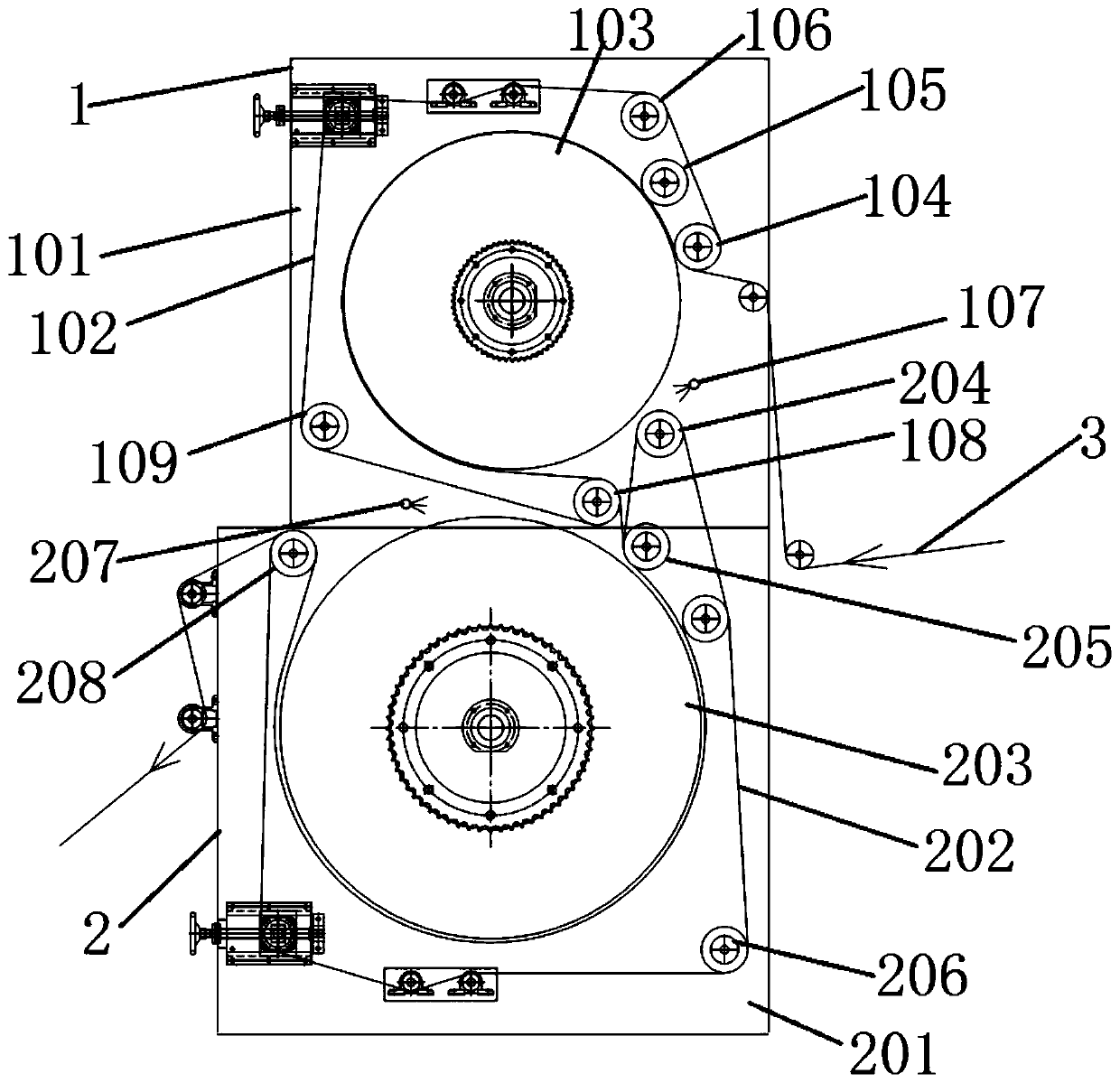
[0055] see Figure 1 to Figure 5 and Figure 9 to Figure 11 , a steaming unit provided with an elastic sealing device provided in this embodiment, comprising:

[0056] Cloth front steaming device 1 arranged sequentially along the conveying direction of the cloth;

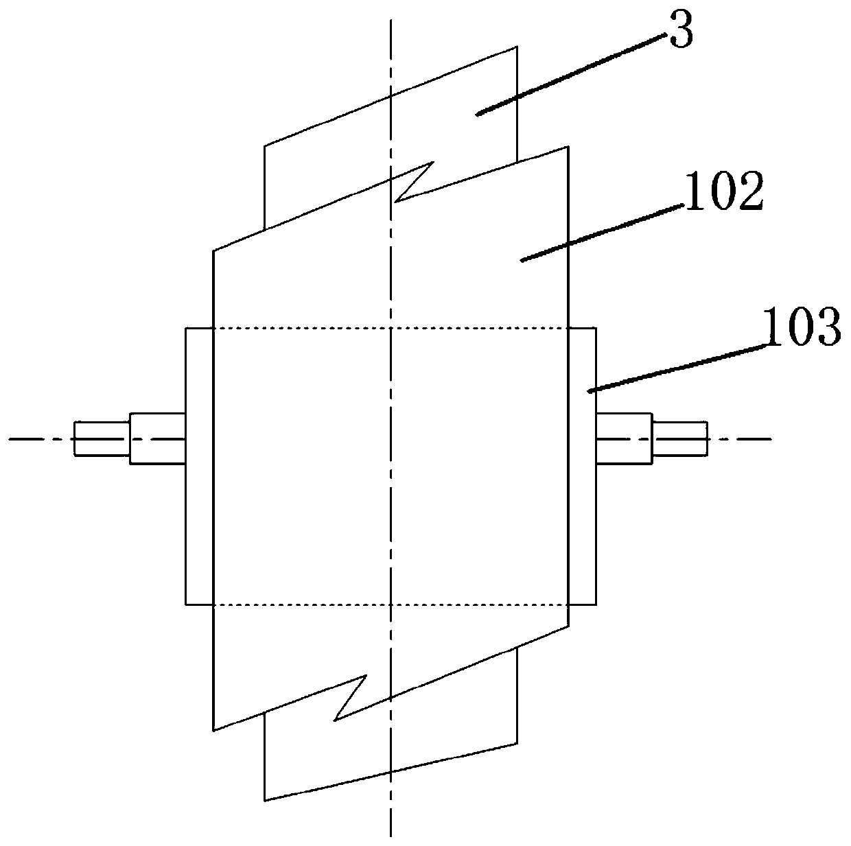
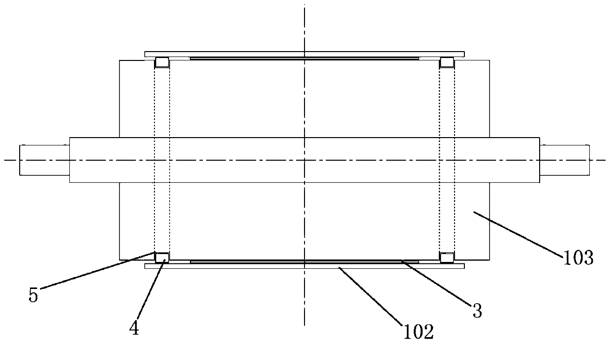
[0057] The cloth front steaming device 1 includes a first frame 101, a first drive assembly, a first heating wheel 103, a first high temperature resistant conveyor belt 102, a first inlet pressure wheel 105 and a first support wheel 106 group, the The first driving assembly is arranged on the first frame 101, the first driving assembly is connected with the first heating large wheel 103, and the first driving assembly is used to drive the first heating large wheel 103 Rotate, the first inlet pressure wheel 105 is one or more, the first support wheel 106 group includes a plurality of first support wheels 106 and the first inlet support wheel 104 and the first outlet support wheel 108, the first A high-temperature-...

Embodiment 2

[0106] see Figure 1 to Figure 11 , a dyeing machine provided in this embodiment, comprising a cloth sending device 6, a finished product collecting device 7, and a double-sided steaming unit according to any one of claims 1 to 5, the cloth sending device 6, the cloth The front steaming device 1 , the cloth reverse steaming device 2 and the finished product collecting device 7 are arranged in sequence along the conveying direction of the cloth.

[0107] Further, it also includes a cooling device 9 arranged between the cloth reverse side steaming device 2 and the finished product collecting device 7, and the cooling device 9 is a cooling wheel group cooling device 9 or a single-sided air-cooled cooling device 9 or a double-sided air-cooled Cooling device 9.

[0108] Further, it also includes a double-sided printing and pad coating device 8 or a single-sided printing and pad coating device arranged between the cloth sending device 6 and the cloth front steaming device 1;

[01...


PUM


Abstract

The invention discloses a steaming unit equipped with an elastic sealing device, and a dyeing machine, and aims to solve the technical problem that cloth is relatively shallow in color yield and poorin color fastness caused by not high dye utilization rate due to loss of steam and dye liquid of the existing steaming equipment. The elastic sealing device comprises elastic washers or elastic sealing strips arranged at the two ends of the outer circular surface of a first heating big wheel; the elastic washers or the elastic sealing strips are arranged at the two ends of the outer circular surface of the first heating big wheel in a sleeved mode; the distances between the elastic washers or the elastic sealing strips arranged at the two ends of the outer circular surface of the first heatingbig wheel is smaller than the width of a first high-temperature-resistant conveyor belt; the high-temperature-resistant conveyor belt is arranged in a working region of the outer circular surface ofthe first heating big wheel; and the left and right ends of the working region of the high-temperature-resistant conveyor belt, and the two elastic washers or the elastic sealing strips arranged on the outer circular surface of the first heating big wheel are arranged in a pressing mode.

Description

technical field [0001] The invention relates to the technical field of cloth dyeing, in particular to a steaming unit and a dyeing machine provided with an elastic sealing device. Background technique [0002] As we all know, disperse dyes will be sublimated into gas under certain temperature conditions, and a considerable part of the dye molecules in the traditional thermosol sublimation dyeing process are not absorbed in the fabric fibers after sublimation, but volatilize into the atmosphere , so the traditional dyeing equipment and dyeing methods have problems such as low dye utilization rate, shallow color yield, poor color fastness and pollution of equipment. Reactive dyes need to be kept in high temperature and high humidity conditions Bottom steaming treatment, while the traditional steaming process is open to the fabric. Under high temperature, the moisture carried by the fabric will be vaporized and volatilized, and the humidity of the fabric surface will decrease, ...

Claims


Application Information

Patent Timeline
Patent Type & Authority Applications(China)
IPC IPC(8): D06B19/00D06B23/04D06B3/18B41F15/38B41F15/42B41F15/46B41F15/08F16J15/3284
CPCB41F15/0836B41F15/38B41F15/42B41F15/46D06B3/18D06B19/0076D06B23/04F16J15/3284
Inventor 不公告发明人
Owner 李雅
Why Eureka
Try Eureka