Damping oil pressure damper for steel structure connection nodes

A technology for connecting nodes and steel structures. It is used in underwater structures, infrastructure engineering, earthquake resistance, etc. to achieve the effects of reasonable structural design, energy dissipation and vibration, and increased damping.

Active Publication Date: 2020-06-12
CHINA NAT OFFSHORE OIL CORP +2
View PDF6 Cites 3 Cited by
  • Summary
  • Abstract
  • Description
  • Claims
  • Application Information

AI Technical Summary

Problems solved by technology

[0003] Aiming at the deficiencies and problems still existing in the shock absorbing dampers currently applied to steel structure nodes, the present invention provides a shock absorbing oil pressure damper for steel structure connecting nodes, which controls the energy dissipation effect by automatically changing the smoothness of the damping medium

Method used


Image

  • Damping oil pressure damper for steel structure connection nodes
  • Damping oil pressure damper for steel structure connection nodes
  • Damping oil pressure damper for steel structure connection nodes

Examples


Embodiment 1

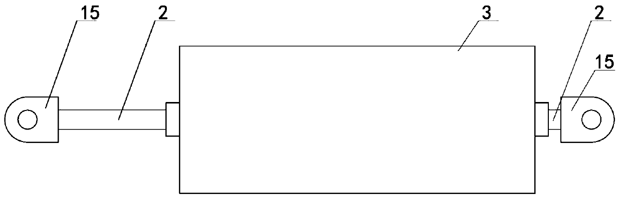
[0022] Embodiment 1: The first type of shock-absorbing oil pressure damper is mainly used in the connection position of the connection node of the steel structure. The damper includes a front tie rod 1, a rear tie rod 2 and a tubular node box 3, such as figure 1 As shown, the front and rear pull rods are also fixed with connecting seat 15. The shock-absorbing oil pressure damper can automatically adjust the change of oil resistance, thereby changing the vibration frequency and vibration amplitude of the node, and can effectively dissipate energy and reduce vibration.

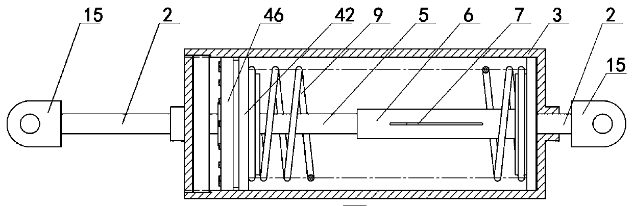
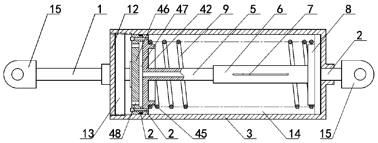
[0023] figure 2 with image 3 respectively figure 1 Schematic diagram of the internal structure of figure 2 with image 3 It can be seen that the node box is a closed structure, and its inner cavity is required to be filled with damping oil to form an oil cavity 14 .

[0024] Such as image 3 As shown, the front end of the oil chamber in the node box is matched with a piston body and additional componen...

Embodiment 2

[0028] Embodiment 2: The shock-absorbing oil pressure damper of the second steel structure connection node, such as Figure 4 As shown, it includes a front tie rod 1 , a rear tie rod 2 and a tubular node box 3 . Wherein, the node box is a closed structure, and its inner cavity is filled with damping oil to form an oil cavity 14 . The front tie rod and the rear tie rod go through the central holes of the two end walls of the node box.

[0029] Such as Figure 5 As shown, the middle part of the oil chamber in the node box 3 is matched with a piston body. There are dynamic spring seats on both sides of the piston body, and fixed spring seats are respectively arranged on the inner walls of both ends of the node box. Thrust springs are respectively connected between the moving spring seat and the fixed spring seat.

[0030] The specific structure of the piston body is as follows: Image 6As shown, it is a composite piston formed by docking and fixing two single pistons (piston ...


PUM


Abstract

The invention discloses a damping oil pressure damper for connection nodes in a steel structure, which comprises a front pull rod, a rear pull rod and a tubular node box, wherein the node box is of aclosed structure, the inner cavity of the node box is filled with damping oil to form an oil cavity, the middle of the oil cavity in the node box is sleeved with a piston body in a matched manner, andthrust springs are respectively connected between a movable spring seat and a fixed spring seat on two sides of the piston body; a sliding pipe is axially fixed at the axial center position of the piston body, two ends of the sliding pipe are respectively matched and sleeved in sliding sleeves at the two ends and are capable of sliding, and strip-shaped oil-saving holes are formed in the side surfaces of the sliding sleeves at the two ends. According to the invention, when the front pull rod and the rear pull rod of the node box are pulled or compressed, the piston body inside the node box can be driven to move in the axial direction, and then the sliding pipe is driven to slide in the sliding sleeve, so that oil resistance change adjustment can be automatically carried out, vibration frequency and vibration amplitude of the nodes are changed, and energy can be effectively dissipated and vibration can be reduced.

Description

technical field [0001] The invention belongs to the technical field of shock absorption and damping of steel structure nodes, and in particular relates to a shock absorption oil pressure damper for steel structure connection nodes. Background technique [0002] The offshore steel structure has a large amount of construction and a large number of nodes. It will be impacted by huge waves and typhoons during and after the construction process, causing the engineering building to sway and vibrate. It is necessary to take necessary shock-absorbing and damping measures for each node of the steel structure project. Existing shock absorbers include those using springs for shock absorption or damping media for shock absorption, or shock absorbers that combine springs and damping media, or dampers that use complex oil circuits. For example, the announcement number is CN 207122541 U provides a damping buffer with a spring, the buffer includes an oil cylinder, and a piston assembly is h...

Claims


Application Information

Patent Timeline
Patent Type & Authority Applications(China)
IPC IPC(8): E02B17/00E04B1/98E04H9/02
CPCE02B17/0004E04B1/98E04H9/021
Inventor 张宁冯丽梅蒲定魏立缪青海魏群
Owner CHINA NAT OFFSHORE OIL CORP
Why Eureka
Try Eureka