A light-driven vibration motor device based on optical fiber

A vibration motor and light-driven technology, applied in the field of optical fiber micro-nano technology research, can solve the problems of difficult capture of absorbing particles and few researches on absorbing particles, and achieve the effect of simple preparation method, simple structure and low price

Active Publication Date: 2020-04-07
HARBIN ENG UNIV
View PDF5 Cites 3 Cited by
  • Summary
  • Abstract
  • Description
  • Claims
  • Application Information

AI Technical Summary

Problems solved by technology

So far, the methods and technologies for manipulating transparent non-absorbing particles are very mature, but there are few studies on manipulating absorbing particles, especially absorbing particles suspended in a liquid background
The main difficulty in trapping strongly absorbing particles in liquids is that there is more absorption on the illuminated side, which will induce forward photophoretic force to push the particles away from the region with high laser optical power density, and the absorbing particles will be affected by the stronger Difficult to capture scattering forces

Method used


Image

  • A light-driven vibration motor device based on optical fiber
  • A light-driven vibration motor device based on optical fiber
  • A light-driven vibration motor device based on optical fiber

Examples


specific Embodiment 1

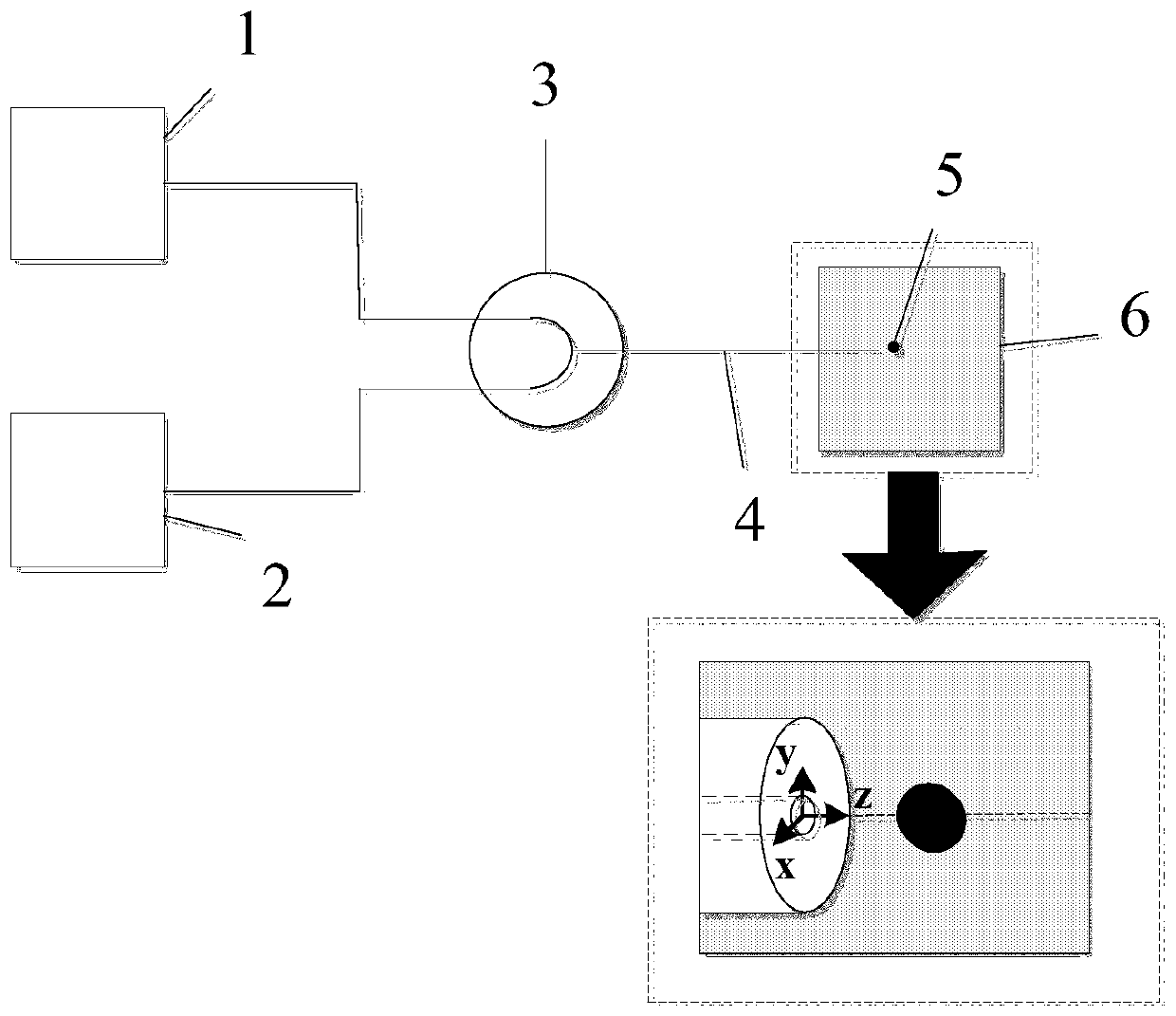
[0036] Such as image 3 As shown, a light-driven vibration motor based on optical fiber includes a first optical fiber light source 1, a second optical fiber light source 2, a 980nm-1550nm optical fiber wavelength division multiplexer 3, a 980nm single-mode optical fiber 4, and a 6 μm absorbing black ball 5 , Glycerin 6.

[0037] 1. Take a section of single-mode optical fiber 4 with a length of about 1 meter. Strip off the coating layer of the optical fiber at one end of the single-mode optical fiber 4 for 20-30mm. Use a non-woven cloth to dip in a mixture of alcohol and ether, and wipe the outer cladding of the optical fiber repeatedly. until cleaned and ready for use;

[0038] 2. Cut the end face of the cleaned single-mode optical fiber 4 flat with an optical fiber cutter;

[0039] 3, use the method in steps 1 and 2 to the laser first optical fiber light source 1 of 980nm wavelength, the second optical fiber light source 2 of 1550nm wavelength laser and the pigtail of the ...


PUM

PropertyMeasurementUnit
diameteraaaaaaaaaa
densityaaaaaaaaaa

Abstract

The invention belongs to the research field of the optical fiber micro-nanotechnology, in particular to an optical-driven vibration motor device capable of stably changing the position and the vibration frequency of absorbent particles. The device comprises an optical tweezers system consisting of a first optical fiber light source, a second optical fiber light source, an optical fiber wavelengthdivision multiplexer and a single-mode optical fiber, and the optical tweezers system, an absorbent black sphere and liquid form the optical-driven vibration motor device. Two kinds of photophoretic forces are used to play an optical driving role on the absorbent particles, the absorbent black sphere can be stably captured in a non-contact mode, and the position and the vibration frequency of theabsorbent black sphere driven by the optical-driven vibration motor can be controlled. The position and the vibration frequency of absorbent particles can be changed and driven at the same time through changing the power of two light sources; the position of the device is accurately controlled and the structure is simple; the absorbent particles in the liquid background can be easily optically driven; and the adopted device is low in price, the making method is simple, and the device is suitable for being promoted in the field of biomedicine.

Description

technical field [0001] The invention belongs to the research field of optical fiber micro-nano technology, and in particular relates to a light-driven vibration motor device capable of stably changing the position and vibration frequency of absorbing particles. Background technique [0002] Optical tweezers were first proposed by American scientist Ashkin and his colleagues in 1986 as a tool for exploring the microscopic world. Optical tweezers use the physical properties of light to trap and manipulate particles. It has the advantage of working in a gentle and non-contact manner. The center of the focused laser beam in the optical tweezers system has a trapping area. Once the particle falls into this area, it will automatically move to the geometric center of the beam, so as to achieve the function of particle trapping; and once it falls into the beam geometry The particles in the center will always be captured if there is no strong external interference, that is, they wi...

Claims


Application Information

Patent Timeline
Patent Type & Authority Patents(China)
IPC IPC(8): G21K1/00
CPCG21K1/006
Inventor 刘志海林思雨汤晓云张亚勋张羽杨军苑立波
Owner HARBIN ENG UNIV
Why Eureka
Try Eureka