Gas hydrate production well structure

A technology of hydrate and natural gas, which is applied in the fields of mining fluid, coal gasification, underground mining, etc., can solve the problems of high cost and large energy loss, and achieve the effect of stable mining and saving energy expenditure

Active Publication Date: 2021-10-26
CHINA UNIV OF PETROLEUM (EAST CHINA) +2
View PDF8 Cites 0 Cited by
  • Summary
  • Abstract
  • Description
  • Claims
  • Application Information

AI Technical Summary

Problems solved by technology

[0004] The purpose of the present invention is to provide a natural gas hydrate production well structure to solve the problems of large energy loss and high cost

Method used


Image

  • Gas hydrate production well structure

Examples


Embodiment Construction

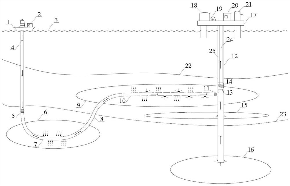
[0024] Specific embodiments of the present invention will be described in detail below in conjunction with the accompanying drawings. It should be understood that the specific embodiments described here are only used to illustrate and explain the present invention, and are not intended to limit the present invention.

[0025] In the present invention, in the case of no contrary description, the used orientation words such as "upper and lower" usually refer to the positional relationship of the natural gas production well structure in the state of installation and use; and, the "well" mentioned in this scheme ", can be the well structure formed by the formation structure itself, that is, the hole formed in the formation structure, or a tubular structure made artificially.

[0026] The present invention provides a natural gas hydrate production well structure, wherein the natural gas hydrate production well structure comprises:

[0027] natural gas production wells 12;

[0028...


PUM


Abstract

The invention relates to the field of natural gas production, and discloses a natural gas hydrate production well structure, comprising: a natural gas production well (12); an injection well (4), and the injection well (4) can be extended to a geothermal layer and can be injected into a heat-carrying well Fluid; heating horizontal well (7), heating horizontal well (7) can be set in geothermal layer (6), heating horizontal well (7) is connected to injection well (4); hydrate production horizontal well (10), hydrate The production horizontal well (10) can be arranged in the shallow hydrate occurrence area (9), and the hydrate production horizontal well (10) is connected to the heating horizontal well (7) and the natural gas production well (12). Through the above technical scheme, the heat in the geothermal layer can be used to decompose the natural gas hydrate in the shallow hydrate occurrence area, so that the decomposed natural gas enters the horizontal well for hydrate exploitation and enters the natural gas production well, which saves energy expenditure and realizes natural gas hydrate. Rapid and stable production of hydrates.

Description

technical field [0001] The invention relates to the field of natural gas production, in particular to the structure of a natural gas hydrate production well. Background technique [0002] Gas hydrate is a kind of clean energy with abundant reserves, which is widely distributed in the continental permafrost zone, polar body continental shelf, deep water environment of ocean and some inland lakes in nature. The global hydrate organic carbon content is twice the total content of other fossil energy sources, and it is expected to become a new energy source that can replace traditional fossil fuels. [0003] The heat injection method usually refers to the use of hot fluid injection to increase the system temperature in the reservoir to promote the decomposition of natural gas hydrate. It has the advantages of convenient operation, fast development speed, and good controllability, but it has high cost, large energy loss, and The defect of low thermal energy utilization rate. Co...

Claims


Application Information

Patent Timeline
Patent Type & Authority Patents(China)
IPC IPC(8): E21B43/24E21B43/295E21B43/30E21B43/01F24T10/20
CPCE21B43/24E21B43/295E21B43/305E21B43/01F24T10/20E21B41/0099E21B43/0107E21B43/12E21B17/01E21B34/06E21B43/08E21B43/128E21B43/38
Inventor 孙宝江欧维·托比亚斯·古德梅斯塔德李学峰刘大辉陈立涛
Owner CHINA UNIV OF PETROLEUM (EAST CHINA)
Why Eureka
Try Eureka