Eureka AIR delivers breakthrough ideas for toughest innovation challenges, trusted by R&D personnel around the world.

Steam turbine lubricating oil system pipeline flushing method

A pipeline flushing and lubricating oil technology, which is applied to chemical instruments and methods, cleaning methods and utensils, mechanical equipment, etc., can solve the problems of time-consuming and manpower consumption, loss of lubricating oil, jamming of the speed control system, etc., and reduce hard The effect of removing impurities such as grains, prolonging the service life, and advancing the completion time

Active Publication Date: 2020-06-12
SANMEN NUCLEAR POWER CO LTD
View PDF3 Cites 1 Cited by
  • Summary
  • Abstract
  • Description
  • Claims
  • Application Information

AI Technical Summary

Problems solved by technology

[0003] The existence of impurities in the lubricating oil system will cause friction between the various parts as the steam turbine running time increases, and at the same time, a large amount of lubricating oil will be lost, which will weaken the flexibility of the various parts of the steam turbine, make the steam turbine not operate normally, and damage the running parts The stability between them, and if the operation time is too long, it may also make the steam turbine work load too heavy, and then damage the steam turbine
Moreover, due to the rapid flushing of impurities and high oil pressure, the cover effect of the steam turbine cannot be fully exerted, resulting in excessive oil pressure swings
And in the speed control system of the steam turbine, because the various pulses of the operation change differently and the range is small, the excessive swing of the oil pressure will also affect the excessive swing of the speed control system, and even cause the speed control system to generate load
In addition, during the operation of the steam turbine, the change of oil pressure is closely related to each speed control system, so the impurities in the lubricating oil system will also affect other speed control systems, causing the speed control system to jam, which will seriously damage the Caused the steam turbine out of control, causing a safety accident
[0004] In order to provide safe and reliable lubricating and cooling oil for steam turbine bearings, the lubricating oil system of steam turbines is usually finely designed, with a large number of equipment and complicated pipeline layout. Therefore, it is difficult to flush the lubricating oil system, and it will consume a lot of time and manpower

Method used


Image

  • Steam turbine lubricating oil system pipeline flushing method
  • Steam turbine lubricating oil system pipeline flushing method
  • Steam turbine lubricating oil system pipeline flushing method

Examples


Embodiment Construction

[0048] The technical solutions of the present invention will be further described below in conjunction with the accompanying drawings and through specific implementation methods.

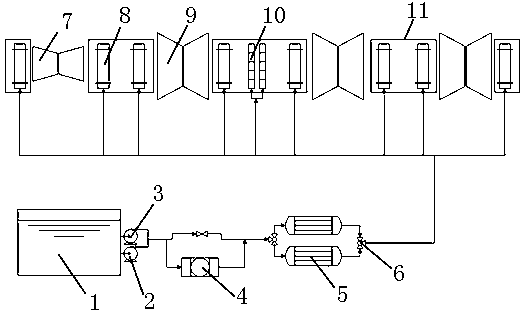
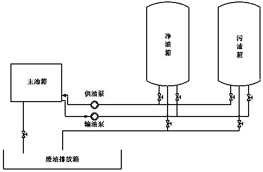
[0049] like figure 2 and 3 As shown, the steam turbine lubricating oil system of the present application may include a main oil tank 1, an AC lubricating oil pump 2 and a DC lubricating oil pump 3 arranged in parallel, a filter 4 and a straight-through valve arranged in parallel, two oil coolers 5 arranged in parallel, and a bearing box 11. Low-pressure cylinder 7, high-pressure cylinder 9, clean oil tank, dirty oil tank, oil delivery pump, oil supply pump and waste oil discharge box.

[0050]The main oil tank 1 is equipped with an oil return filter, the inlet and outlet ports of the AC lubricating oil pump 2 and the DC lubricating oil pump 3 arranged in parallel are connected with the main oil tank 1 through the oil supply pipeline, and the filter 4 and the straight-through valve arranged in para...


PUM


Abstract

The invention relates to the technical field of lubricating oil flushing, in particular to a steam turbine lubricating oil system pipeline flushing method. The method comprises the following steps that 1, manually cleaning the interiors of a main oil tank, a clean oil tank and a dirty oil tank through cleaning substances; 2, injecting temporary flushing oil into the cleaned clean oil tank or dirtyoil tank; 3, circularly flushing the temporary flushing oil among the main oil tank, the clean oil tank, the dirty oil tank and the connecting pipeline through an oil supply pump and an oil deliverypump until the total amount of impurities collected by the oil return filter screen does not exceed 1.0 g after the flushing time is 8 hours, and completely discharging the temporary flushing oil to an outdoor oil storage device; 4, manually cleaning the interiors of the main oil tank, the clean oil tank and the dirty oil tank through cleaning substances; and 5, confirming that necessary temporarymeasures are completed. According to the steam turbine lubricating oil system pipeline flushing method, the cleanliness of the steam turbine auxiliary lubricating oil system pipeline can be greatly improved, and guarantee is provided for safe, stable and reliable operation of a steam turbine and an auxiliary system thereof.

Description

technical field [0001] The invention relates to the technical field of lubricating oil flushing, in particular to a pipeline flushing method for a lubricating oil system of a steam turbine. Background technique [0002] The lubricating oil system of the turbogenerator set is an important subsidiary system of the turbogenerator set. Its main function is to provide lubricating oil for the supporting bearings, thrust bearings and turning gear of the turbogenerator set. The sealing oil system provides a backup oil source to ensure the needs of the unit in normal operation and accident conditions. Pipeline flushing of lubricating oil system is a safe and reliable method to remove all external impurities that may enter the oil system, so as to avoid damage to steam turbine bearings caused by impurities. [0003] The existence of impurities in the lubricating oil system will cause friction between the various parts as the steam turbine running time increases, and at the same time,...

Claims


Application Information

Patent Timeline
Patent Type & Authority Applications(China)
IPC IPC(8): F01D25/00B08B9/08B08B9/093B08B9/027B08B9/032
CPCF01D25/002B08B9/08B08B9/093B08B9/027B08B9/0321
Inventor 王雄楼安平刘超
Owner SANMEN NUCLEAR POWER CO LTD
Why Eureka
Eureka Blog
Learn More