Wind power generation tower convenient to maintain
A technology of wind power generation and electric motor, which is applied in the direction of wind power generation, wind engine, wind motor combination, etc. It can solve the problems of waste of energy, low safety, time-consuming and laborious, etc., and achieve the effect of simple structure and convenient operation
- Summary
- Abstract
- Description
- Claims
- Application Information
AI Technical Summary
Problems solved by technology
Method used
Image

Examples
Embodiment Construction
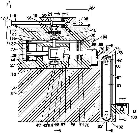
[0020] Combine below Figure 1-Figure 7 The present invention is described in detail, and for convenience of description, the orientations mentioned below are now stipulated as follows: figure 1 The up, down, left, right, front and back directions of the projection relationship itself are the same.
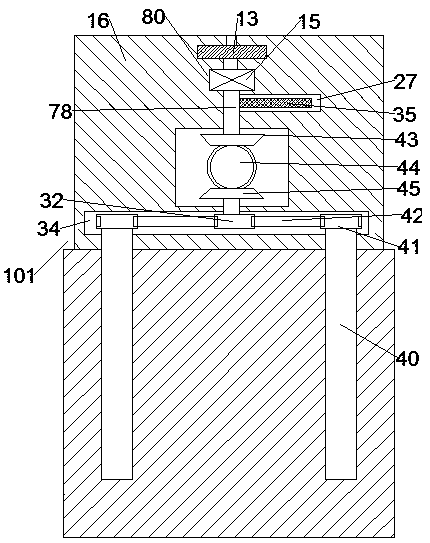
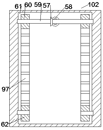
[0021] A maintenance-friendly wind power generation tower according to the present invention includes a load-bearing box 64, a power box 16 is arranged on the upper side of the load-bearing box 64, and the lower end of the power box 16 is symmetrical in front and rear and is connected with threads in rotation. Connected to the screw rod 40 in the load-bearing box 64, the bottom of the power box 16 is provided with a pulley mechanism 101 that drives the screw rod 40 on the front and rear sides to rotate synchronously, and the right side of the load-bearing box 64 is provided with The sprocket mechanism 102, the sprocket mechanism 102 includes a synchronous sprocket cavity 61 arran...
PUM
 Abstract
Description
Claims
Application Information
 - Generate Ideas
- Intellectual Property
- Life Sciences
- Materials
- Tech Scout
- Unparalleled Data Quality
- Higher Quality Content
- 60% Fewer Hallucinations
Browse by: Latest US Patents, China's latest patents, Technical Efficacy Thesaurus, Application Domain, Technology Topic, Popular Technical Reports.
© 2025 PatSnap. All rights reserved.Legal|Privacy policy|Modern Slavery Act Transparency Statement|Sitemap|About US| Contact US: help@patsnap.com