Differential pressure sensor based on optical fiber point type sensor

A differential pressure sensor and sensor technology, applied in fluid pressure measurement using optical methods, pressure difference measurement between multiple valves, instruments, etc., can solve the problems of being unable to apply to high static pressure and high temperature environments, and avoid being affected Damage, Avoidance of measurement errors, Effect of high sensitivity

Active Publication Date: 2020-06-12
UNIV OF ELECTRONIC SCI & TECH OF CHINA
View PDF8 Cites 5 Cited by
  • Summary
  • Abstract
  • Description
  • Claims
  • Application Information

AI Technical Summary

Problems solved by technology

[0003] Aiming at the above-mentioned deficiencies in the prior art, the present invention provides a differential pressure sensor based on an optical fiber point sensor to solve the problem that the prior art cannot be applied to high static pressure and high temperature environments

Method used


Image

  • Differential pressure sensor based on optical fiber point type sensor
  • Differential pressure sensor based on optical fiber point type sensor
  • Differential pressure sensor based on optical fiber point type sensor

Examples


Embodiment Construction

[0026] The specific embodiments of the present invention are described below so that those skilled in the art can understand the present invention, but it should be clear that the present invention is not limited to the scope of the specific embodiments. For those of ordinary skill in the art, as long as various changes Within the spirit and scope of the present invention defined and determined by the appended claims, these changes are obvious, and all inventions and creations using the concept of the present invention are included in the protection list.

[0027] Embodiments of the present invention will be described in detail below in conjunction with the accompanying drawings.

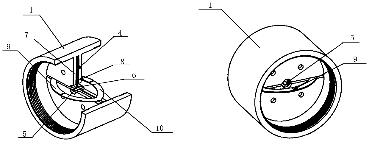
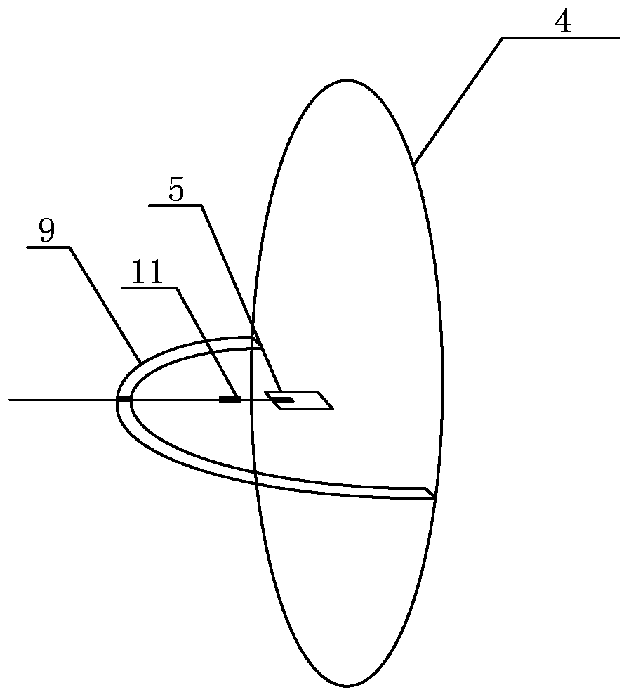
[0028] Such as Figure 1-Figure 3 Commonly shown, a differential pressure sensor based on a fiber optic point sensor, including a housing 1, a first pressure introduction tube 2, a second pressure introduction tube 3, a first fiber optic point sensor 11, a second fiber optic point sensor 12 , a fir...


PUM


Abstract

The invention discloses a differential pressure sensor based on an optical fiber point type sensor, and the differential pressure sensor is provided with a first limiting diaphragm and a second limiting diaphragm, thereby guaranteeing that a pressure sensing diaphragm cannot be damaged irreversibly, and guaranteeing that the deformation of the pressure sensing diaphragm is not hindered in a measurement range. The fixing points of the pressure sensing diaphragm, the first arc-shaped metal sheet and the second arc-shaped metal sheet are located at the same position, so that measurement errors caused by deformation of the shell are avoided, and the measurement precision is improved. By arranging the first optical fiber point type sensor and the second optical fiber point type sensor, the pressure difference is converted into the change of the characteristic value of the optical fiber point type sensors, and the characteristics of high sensitivity and long-term stability are achieved. Dueto the fact that the limiting diaphragms are arranged, the pressure sensing diaphragm can be made of chromium-nickel alloy, the material of the pressure sensing diaphragm can be selected according tothe using environment, and the differential pressure sensor can be suitable for high-static-pressure and high-temperature environments.

Description

technical field [0001] The invention belongs to the field of fluid pressure testing, in particular to a differential pressure sensor based on an optical fiber point sensor. Background technique [0002] Differential pressure sensors are an important part of process control systems. The flow rate is measured by the pressure difference generated when flowing through the throttling device. It is widely used in the measurement, control and regulation of fluid flow in the production process of petroleum, chemical industry, metallurgy, textile, electric power, navigation, aviation, electromechanical and other industrial sectors. The differential pressure sensors commonly used in the prior art are electronic (resistive, voltage, etc.), which have many application limitations, are susceptible to electromagnetic interference, have too many communication and power supply cables, and cannot tolerate high static pressure and high temperature environments, etc. . Contents of the inven...

Claims


Application Information

Patent Timeline
IPC IPC(8): G01L13/00G01L19/00G01L19/06G01L11/02
CPCG01L13/00G01L19/00G01L19/06G01L11/025
Inventor 冉曾令肖彦波青先国何正熙朱加良何鹏徐思捷向美琼吴茜陈静徐涛
Owner UNIV OF ELECTRONIC SCI & TECH OF CHINA
Why Eureka
Try Eureka