A device and method for in-situ testing the reaction behavior of refractory materials under stress

A technology for in-situ testing of refractory materials, applied in the direction of measuring devices, applying stable tension/pressure to test material strength, analyzing materials, etc., can solve the problem of inability to accurately characterize the damage behavior and mechanism of refractory materials, and cannot take into account the evolution of microstructure online access etc.

Active Publication Date: 2021-12-14
UNIV OF SCI & TECH BEIJING
View PDF8 Cites 0 Cited by
  • Summary
  • Abstract
  • Description
  • Claims
  • Application Information

AI Technical Summary

Problems solved by technology

However, most of the existing test devices do not consider the influence of stress on refractory materials, and the few test devices cannot take into account the online acquisition of the sample quality and microstructural evolution during the reaction process. Therefore, it is impossible to accurately characterize refractory materials. Damage behavior and mechanism under high temperature stress field

Method used


Image

  • A device and method for in-situ testing the reaction behavior of refractory materials under stress
  • A device and method for in-situ testing the reaction behavior of refractory materials under stress
  • A device and method for in-situ testing the reaction behavior of refractory materials under stress

Examples


Embodiment 1

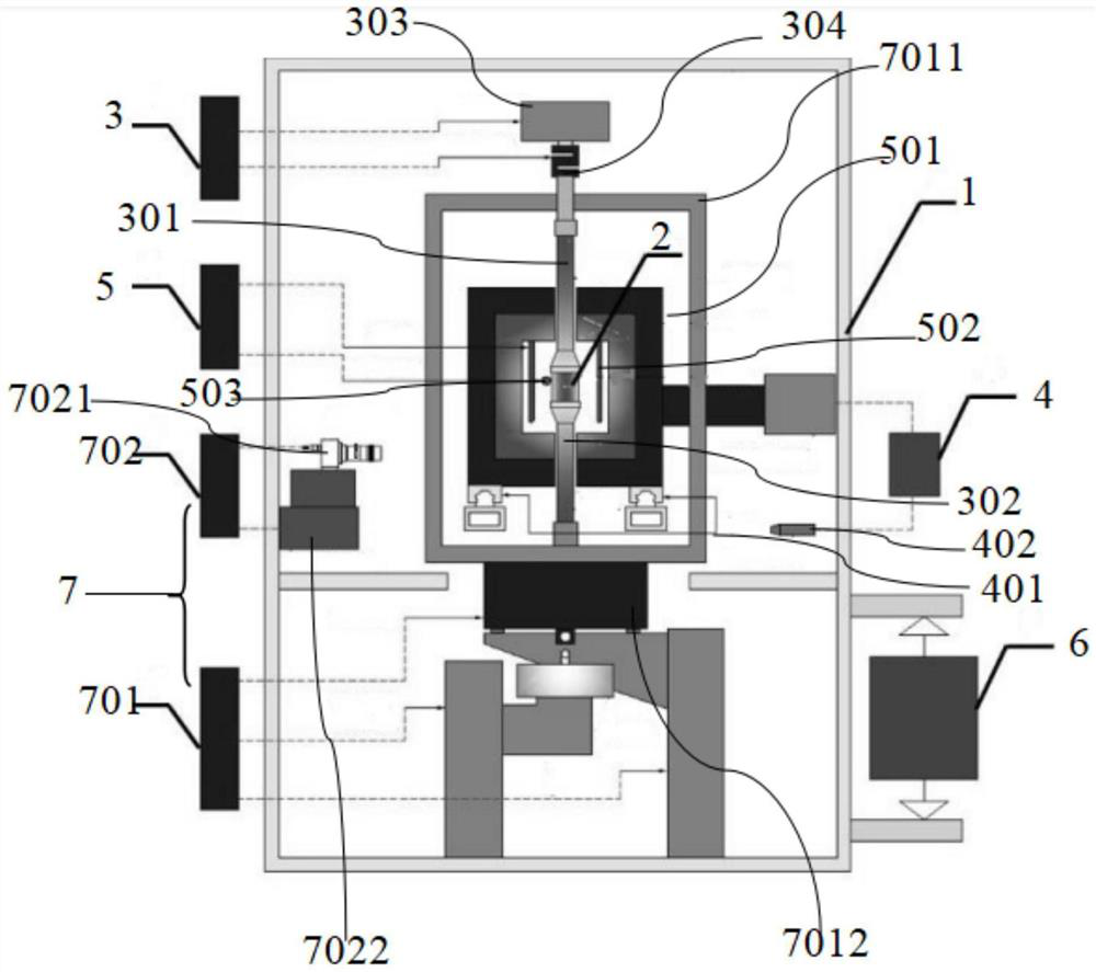
[0058] see figure 1, a device for in-situ testing the reaction behavior of refractory materials under stress, including a stress loading system 3, an air-cooled thermal shock system 4 and a heating system 5 arranged in a sealed cavity 1, and a device connected to the sealed cavity 1 The atmosphere control system 6 and the detection system 7, the stress loading system 3 is used to clamp the sample 2, and provide compressive stress loading to the sample 2 when testing the reaction behavior of the sample 2; the air-cooled thermal shock system 4 is used to test Thermal stress is provided to sample 2 during the reaction behavior of sample 2; heating system 5 surrounds sample 2 and is used to heat sample 2 when testing the reaction behavior of sample 2; atmosphere control system 6 is used to When testing the reaction behavior of the sample 2, a vacuum or a test environment with different atmospheres is provided for the sample 2; the detection system 7 is used for real-time in-situ d...

Embodiment 2

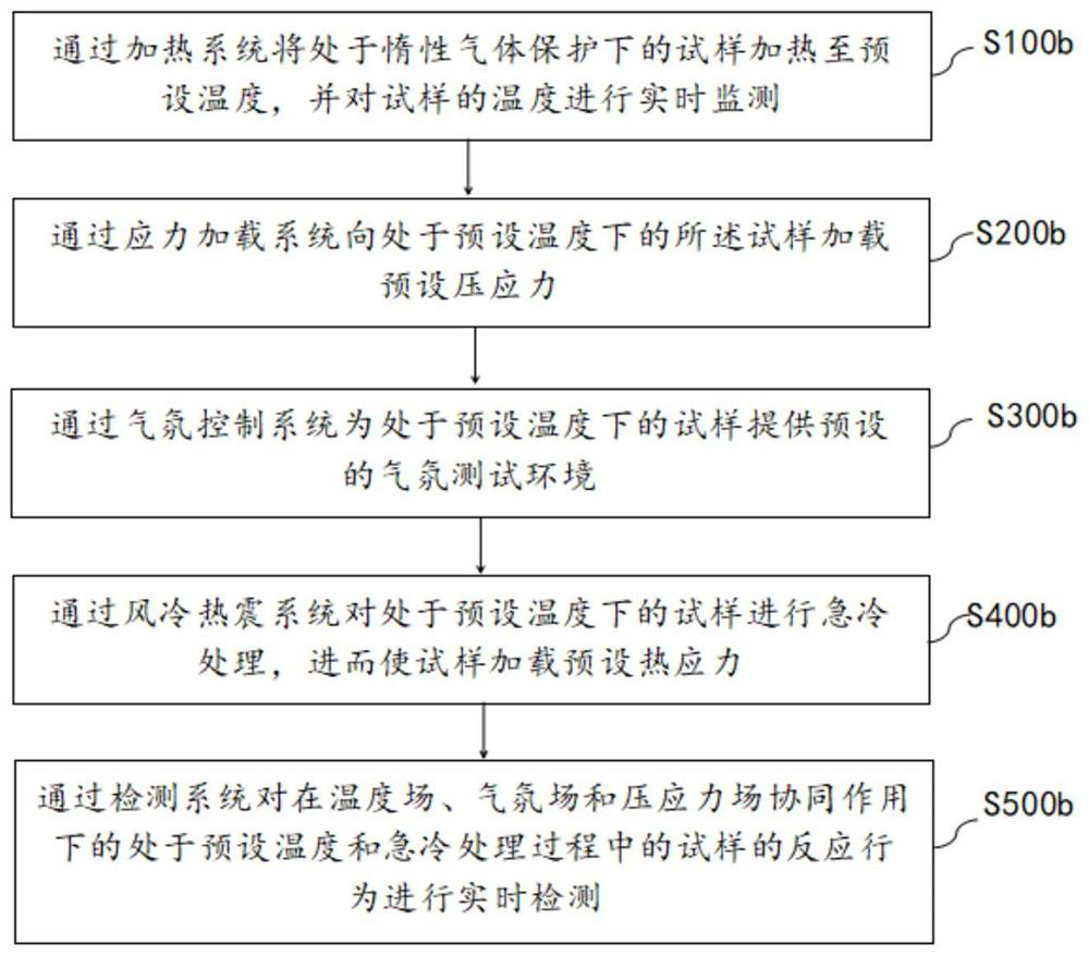
[0081] see image 3 , this embodiment provides a method for in situ testing the reaction behavior of refractory materials under stress, including:

[0082] S100b, heating the sample under the protection of the inert gas to a preset temperature through the heating system, and monitoring the temperature of the sample in real time.

[0083] Specifically, the sample is fixed between the first press bar and the second press bar, and argon gas is introduced into the furnace body through the control atmosphere control system to protect the sample with argon atmosphere, and then the heating system is controlled to raise the temperature of the heating furnace to preset temperature.

[0084] S200b. Apply a preset compressive stress to the sample at a preset temperature through a stress loading system.

[0085] Specifically, the first compression bar is controlled to move in the vertical direction through the loading mechanism, so as to realize the adjustment of the compressive stress ...


PUM


Abstract

The invention discloses a device and method for in-situ testing the reaction behavior of refractory materials under stress, wherein the device includes: a stress loading system for clamping a sample, and when testing the reaction behavior of the sample The sample provides compressive stress loading; the air-cooled thermal shock system is used to provide thermal stress to the sample when testing the response behavior of the sample; the heating system is used to test the response behavior of the sample When the sample is heated; the atmosphere control system is used to provide a vacuum or a test environment of different atmospheres for the sample when testing the reaction behavior of the sample; the detection system is used to test the sample. Real-time in situ detection of reactive behavior. The invention can realize the coordinated control of the temperature field, the atmosphere field and the stress field of the sample during the reaction process, and then perform in-situ testing on the high-temperature reaction behavior of the refractory material under conditions closer to the actual service environment.

Description

technical field [0001] The invention belongs to the technical field of performance research of inorganic non-metallic materials, and in particular relates to a device and method for in-situ testing the reaction behavior of refractory materials under stress. Background technique [0002] Refractory materials are widely used in various fields of national economy such as steel, non-ferrous metals, glass, cement, ceramics, petrochemical, electric power and military industry. It plays an irreplaceable important role in the development of production. However, in practical applications, refractory materials are often subject to frequent temperature changes, scour and extrusion of different reaction media, so they are inevitably affected by thermal stress, compressive stress and thermal-compressive coupling complex stress, which will cause the microstructure of the material to change. Changes, micro-cracks and holes, even cracking and peeling, the resulting material failure often b...

Claims


Application Information

Patent Timeline
Patent Type & Authority Patents(China)
IPC IPC(8): G01N3/18G01N3/02
CPCG01N3/18G01N3/02G01N2203/0003G01N2203/0019G01N2203/005G01N2203/0226G01N2203/0228G01N2203/0244G01N2203/0676G01N2203/0641G01N2203/0236
Inventor 侯新梅王恩会郭春雨刘云松张海军徐林超杨涛陈俊红杨利彬
Owner UNIV OF SCI & TECH BEIJING
Why Eureka
Try Eureka