Full-die-cutting ultrahigh-frequency electronic tag antenna and processing equipment and processing technology thereof

An electronic label, ultra-high frequency technology, applied in the field of ultra-high frequency electronic label antenna and its processing equipment and processing technology

Pending Publication Date: 2020-06-12
黄光伟
View PDF5 Cites 3 Cited by
  • Summary
  • Abstract
  • Description
  • Claims
  • Application Information

AI Technical Summary

Problems solved by technology

[0004] The purpose of the present invention is to provide a fully die-cut UHF electronic tag antenna and its processing equipment and processing technology, mainly to solve the problem in the above-mentioned prior art: how to avoid using the etching process to produce UHF electronic tags The chip bonding point and the chip bon

Method used


Image

  • Full-die-cutting ultrahigh-frequency electronic tag antenna and processing equipment and processing technology thereof
  • Full-die-cutting ultrahigh-frequency electronic tag antenna and processing equipment and processing technology thereof
  • Full-die-cutting ultrahigh-frequency electronic tag antenna and processing equipment and processing technology thereof

Examples


specific Embodiment 2

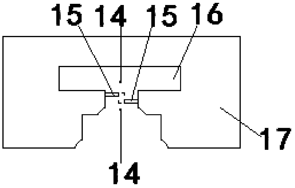
[0095] Specific embodiment 2, specific embodiment 2 is basically the same as this embodiment 1, the difference is: The mechanism is a die-cutting machine that performs flat die-cutting and / or round-knife die-cutting on the chip binding points 15 and the chip binding positioning points 14 at the same time, that is to say, the first die-cutting mechanism completes the chip binding points 15 and 14 at one time. The flat die-cutting and / or the circular knife die-cutting of the chip binding positioning point 14, for example, all the flat die-cutting machines are replaced by the circular knife die-cutting machines. Similar operations are performed to form the antenna layer by one-time flat die-cutting. The chip binding point 15 and the chip binding positioning point 14, that is to say, the die-cutting tool of the flat die-cutting machine will die-cut the chip binding point 15 and the chip binding positioning point 14 on the antenna layer at one time, for example The blade thickness ...

specific Embodiment 3

[0098] The specific embodiment 3, the specific embodiment 3 is basically the same as the present embodiment 1, the difference is: in the production step 5 of the processing technology of the fully die-cut UHF electronic tag antenna in the specific embodiment 3, the The first die-cutting mechanism for die-cutting the chip binding positioning points 14 and the chip binding points 15 and the second die-cutting mechanism 10 for die-cutting the surrounding edges of the antenna body 17 are combined into a flat die-cutting machine or a circular knife die cutting machine.

[0099] That is to say, the first die-cutting mechanism and the second die-cutting mechanism 10 are combined into a flat die-cutting machine or a circular knife die-cutting machine, which can complete the flat die of the chip binding point 15 and the chip binding positioning point 14 at one time. The operation of cutting and / or die-cutting with a circular knife and performing flat die-cutting and / or die-cutting with...


PUM


Abstract

The invention provides a full-die-cutting ultrahigh frequency electronic tag antenna and processing equipment and a processing technology thereof, the full-die-cutting ultrahigh frequency electronic tag antenna comprises an antenna body, and the full-die-cutting ultrahigh frequency electronic tag antenna is characterized in that the antenna body is provided with a chip binding positioning point formed by a die cutting mode and a chip binding point formed by the die cutting mode. According to the invention, the problem of how to avoid applying an etching process to produce the chip binding point and the chip binding positioning point of the ultrahigh frequency electronic tag antenna in the prior art is solved.

Description

technical field [0001] The invention relates to the technical field of electronic tags, in particular to a fully die-cut ultra-high frequency electronic tag antenna and its processing equipment and processing technology. Background technique [0002] At present, the chip binding points and chip binding positioning points of the UHF electronic tag antenna are still produced by the etching process. The etching process requires chemicals such as hydrochloric acid, which has a great impact on the environment. Therefore, how to avoid the use of the etching process to produce ultra-high Chip binding points and chip binding positioning points of high-frequency electronic tag antennas have become problems to be solved urgently. [0003] In addition, how to completely avoid the problem of using the etching process in the production process of the UHF electronic tag antenna has also become an urgent problem to be solved. SUMMARY OF THE INVENTION [0004] The object of the present i...

Claims


Application Information

Patent Timeline
IPC IPC(8): G06K19/077B26F1/38
CPCG06K19/07775G06K19/07786G06K19/07722B26F1/38
Inventor 黄光伟黄金良
Owner 黄光伟
Why Eureka
Try Eureka