Check patentability & draft patents in minutes with Patsnap Eureka AI!

Laminated optocoupler structure with light reflecting part

A technology of reflective part and optocoupler, applied in the direction of electrical components, electro-solid devices, circuits, etc., can solve problems such as reception

Inactive Publication Date: 2020-06-12
喆光照明光电股份有限公司
View PDF4 Cites 0 Cited by
  • Summary
  • Abstract
  • Description
  • Claims
  • Application Information

AI Technical Summary

Problems solved by technology

However, in actual use, some of the light generated by the light emitter still does not go towards the light receiver, and cannot be received by the light receiver. Therefore, how to improve the light collection efficiency becomes the problem to be solved by the present invention. important topic

Method used


Image

  • Laminated optocoupler structure with light reflecting part
  • Laminated optocoupler structure with light reflecting part

Examples


Embodiment Construction

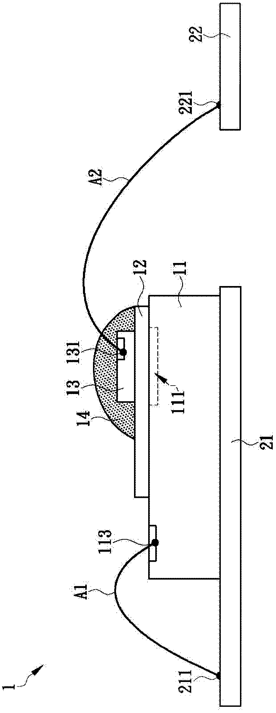
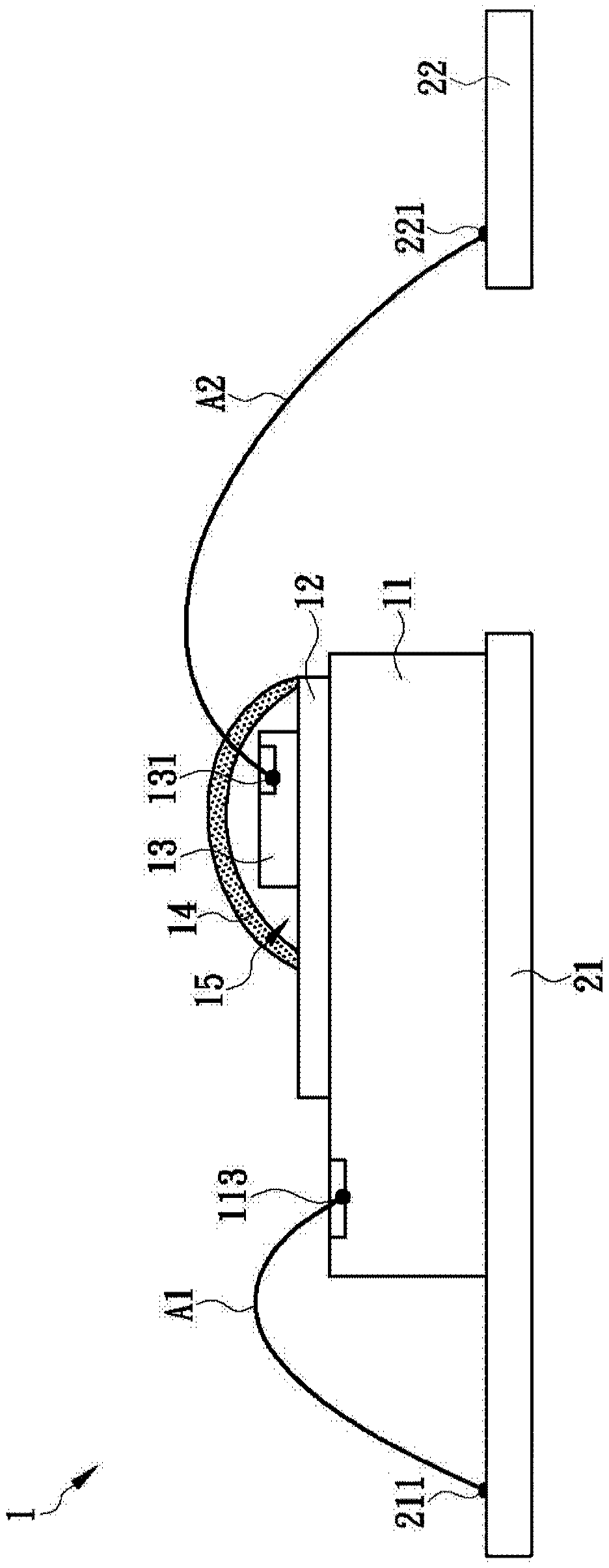
[0026] The present invention is a laminated optocoupler structure with a reflective part, please refer to figure 1 , in one embodiment, the laminated optocoupler structure 1 includes a light receiver 11, an insulating layer 12, a light emitter 13 and a light reflector 14, wherein one side of the light receiver 11 is provided with a light receiving area 111, so as to receive the light from the outside. Moreover, the optical receiver 11 can be fixed (such as welding, inserting or pasting, etc.) to a first substrate 21 (such as a circuit board, bracket, etc.), and a first connecting pin 113 can be provided thereon. , the first connection pin 113 can be electrically connected (eg, wire bonding) to a first contact 211 of the first substrate 21 through a first transmission line A1 .

[0027] see again figure 1 As shown, the insulating layer 12 can cover one side of the light receiver 11, and is provided with a light-transmitting area, and the light-transmitting area can at least c...


PUM


Abstract

The invention discloses a laminated optocoupler structure with a light reflecting part. The structurecomprises a light receiver, an insulating layer, a light emitter and a light reflecting part, the insulating layer, the illuminator and the light reflecting part are sequentially stacked on one side surface of the light receiver from bottom to top; a light source generated by the illuminator can penetrate through the insulating layer and is received by the light receiver; the structure is characterized in that the light reflecting part can directly or indirectly cover at least part of the illuminator and when the light emitted by the light emitter does not face the light receiver, reflects, refracts and / or scatters the light to face the light receiver, so that the overall optical efficiency of the laminated optical coupler structure can be effectively improved, and a large amount of light generated by the light emitter can be transmitted to the light receiver.

Description

technical field [0001] The invention relates to the structure of an optical coupler, in particular to a product with a reflective part added to the laminated optical coupler structure. Background technique [0002] Generally speaking, an optocoupler (optical coupler, or optocoupler, optoisolator, and optoisolator) is a photoelectric conversion component that transmits electrical signals through light (such as: visible light, infrared) as a medium. The receiver and the light emitter are packaged together, and there is no electrical connection between the light receiver and the light emitter except light. [0003] At present, optocouplers are generally divided into "left-right structure" and "up-and-down structure". The following is a brief description. Relative position, wherein, the light emitter and the light receiver will be set on different brackets respectively, and the two brackets are separated from each other by a distance, and will not touch each other, so that the ...

Claims


Application Information

Patent Timeline
Patent Type & Authority Applications(China)
IPC IPC(8): H01L25/16H01L33/60
CPCH01L25/167H01L33/60
Inventor 梁伟成张平
Owner 喆光照明光电股份有限公司
Features
  • R&D
  • Intellectual Property
  • Life Sciences
  • Materials
  • Tech Scout
  • Unparalleled Data Quality
  • Higher Quality Content
  • 60% Fewer Hallucinations
Learn More