
A charging device for a robot with a protective function

A charging device and protection function technology, applied in the field of robots, can solve the problems that affect the normal use of the charging device by users, the charging contacts are easily splashed with water and dust, and the sweeping robot cannot be charged, and achieve simple structure and good protection function , using reliable effects

Active Publication Date: 2021-03-02
肖宏丽
View PDF8 Cites 0 Cited by
  • Summary
  • Abstract
  • Description
  • Claims
  • Application Information

AI Technical Summary

Problems solved by technology

[0004] However, due to the lack of a corresponding protective structure for the charging device, the charging contacts on the charging device are easily splashed with water and dust, resulting in the charging device being unable to charge the sweeping robot, affecting the normal use of the charging device by the user

Method used


Image

  • A charging device for a robot with a protective function
  • A charging device for a robot with a protective function
  • A charging device for a robot with a protective function

Examples


Embodiment 1

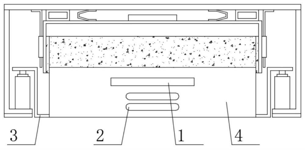
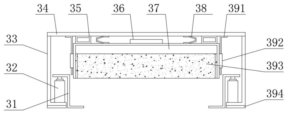
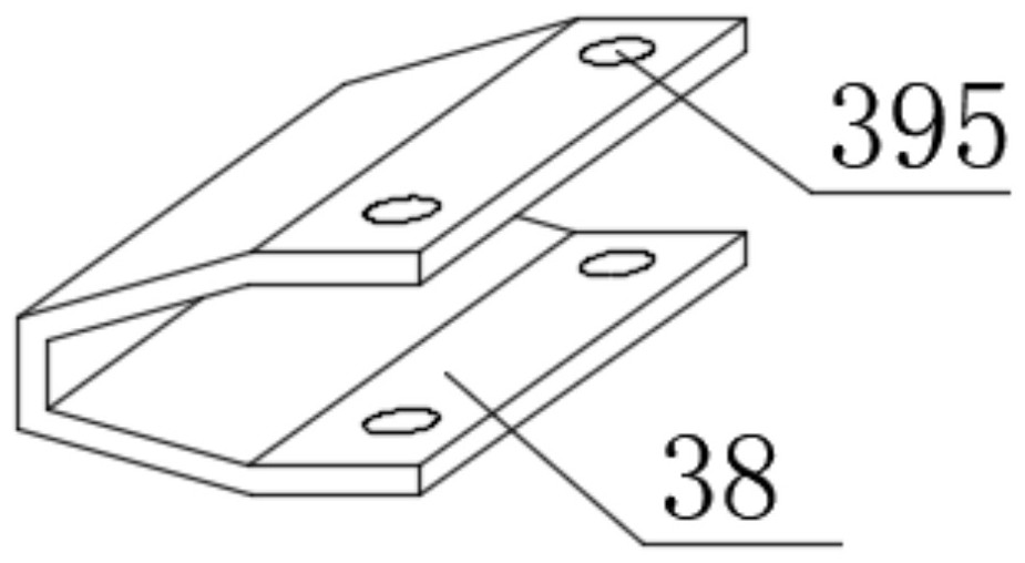
[0023] see Figure 1-Figure 3 , the present invention provides a technical solution: a charging device for a robot with a protective function, comprising a housing 4, a signal transmitter 1 is provided at the top of the housing 4, and a charging contact 2 is provided at the bottom of the housing 4, The use of the housing 4, the signal transmitter 1 and the charging contact 2 are all prior art, the charging contact 2 and the signal transmitter 1 protrude from the housing 4, and the protruding length is 3 mm, and the top of the housing 4 A protective mechanism 3 is provided; the protective mechanism 3 includes a protective top plate 34, the two ends of the lower surface of the protective top plate 34 are provided with supporting legs 33, the bottom end of the supporting legs 33 is provided with an electric telescopic rod 32, and the top of the electric telescopic rod 32 is provided with a The corresponding first limiting member 31 of the housing 4;

[0024] The lower part of th...

Embodiment 2

[0032] On the basis of Embodiment 1, in order to make the vibration effect of the rubber square tube 35 better, in this embodiment, preferably, the rubber square tube 35 is connected with the protective top plate 34 by glue bonding, and the rubber square tube 35 and the protective sleeve The barrel 37 is connected by glue bonding;

[0033] In order to make the support effect of the support feet 33 better, in the present embodiment, preferably, the support feet 33 are "L" shaped structures, the material of the support feet 33 is stainless steel, and the top of the support feet 33 and the protective top plate 34 are fixed by welding connect;

[0034] In order to make the limiting effect of the first limiting member 31 better, in this embodiment, preferably, the first limiting member 31 has a “Z” shape structure, and one end of the first limiting member 31 passes through the electric telescopic rod 32 The welding method is fixedly connected, and the other end of the first limiti...


PUM


Abstract

The invention discloses a charging device for a robot with a protective function, belonging to the technical field of robots. A protective mechanism is arranged above, and the protective mechanism includes a protective top plate. The two ends of the lower surface of the protective top plate are provided with supporting feet, the bottom ends of the supporting feet are provided with electric telescopic rods, and the top of the electric telescopic rods are provided with a first corresponding to the shell. The limiting member, a protective sleeve corresponding to the casing is arranged under the protective top plate, a vibration motor is arranged in the middle of the upper surface of the protective sleeve, and rubber squares corresponding to the protective top plate are arranged on both ends of the upper surface of the protective sleeve. The invention has the advantages of simple structure, convenient use and good protective function, which can effectively prevent the charging contacts on the charging device from splashing with water stains and dust, and the device can clean the charging contacts.

Description

technical field [0001] The invention belongs to the technical field of robots, and in particular relates to a charging device for a robot with a protective function. Background technique [0002] Chinese patent (publication number CN205335915U) discloses an automatic docking charging device for an intelligent sweeping robot, including a sweeping robot charging station and a sweeping robot. The sweeping robot charging station includes a horizontal base plate and a vertical housing; the described The housing is equipped with a main signal transmitter, a top signal transmitter, a charging contact, a DC socket and several LED indicators; the sweeping robot is provided with a charging contact, a middle infrared receiver and an auxiliary receiver. [0003] The advantage of the charging device is that the docking is realized through the infrared signal of the charging station to realize the charging problem of the sweeping robot. [0004] However, because the charging device lacks...

Claims


Application Information

Patent Timeline
Patent Type & Authority Patents(China)
IPC IPC(8): H01R13/502H01R13/52H01R13/60B08B1/00H02J7/00
CPCH01R13/60H01R13/52H01R13/502H02J7/0042B08B1/143B08B1/30
Inventor 肖宏丽
Owner 肖宏丽
Learn More