Rotary vibration motor
A vibration motor and vibration component technology, applied in the direction of electromechanical devices, electrical components, etc., can solve the problems that the vibration effect needs to be improved, the vibration form is single, etc., and achieve the effect of various vibration modes, increasing the vibration effect, and increasing the acceleration.
- Summary
- Abstract
- Description
- Claims
- Application Information
AI Technical Summary
Problems solved by technology
Method used
Image

Examples
Embodiment 1
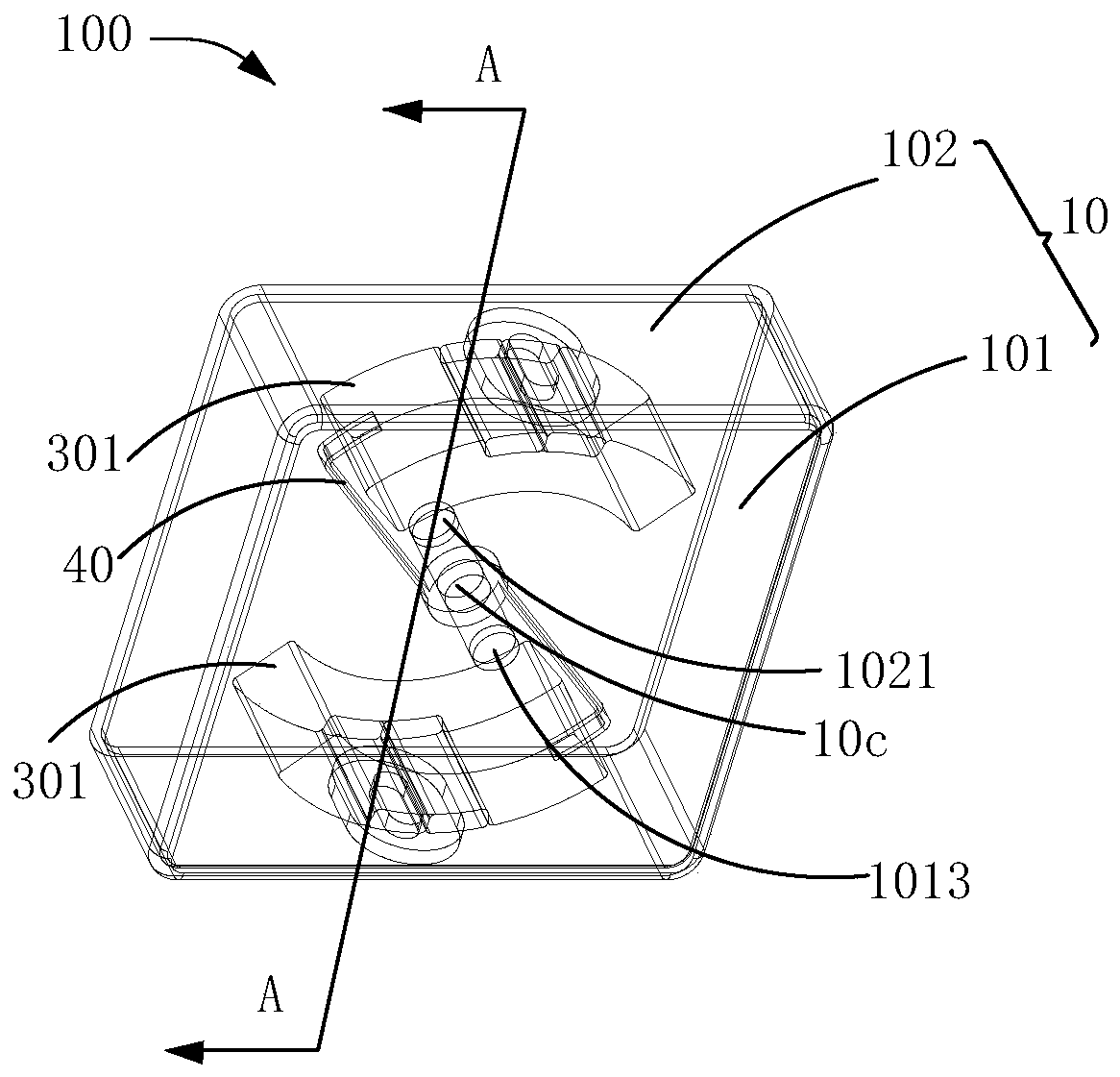
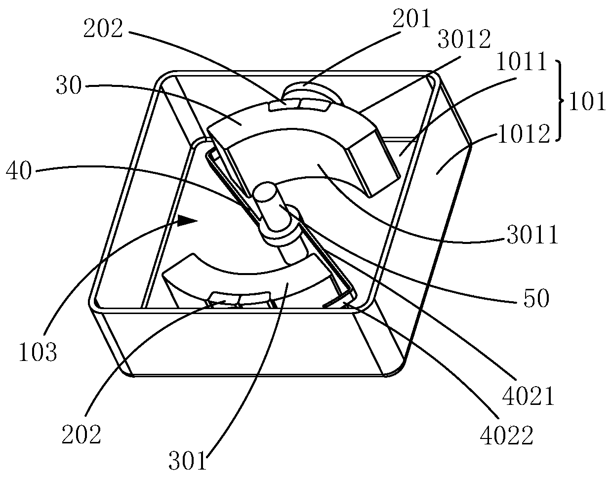
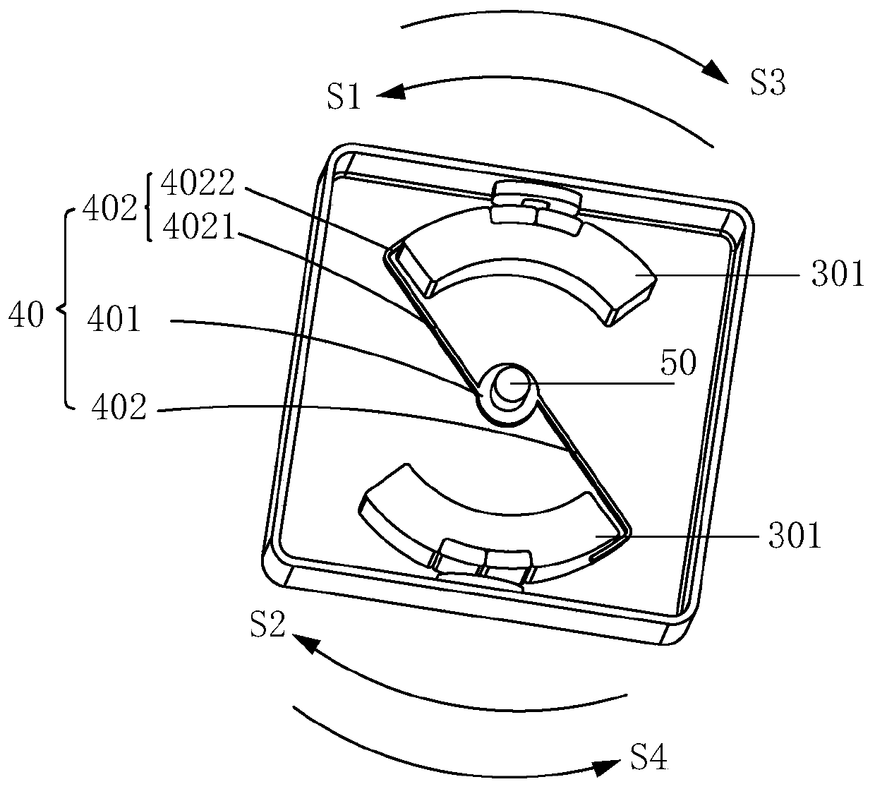
[0041] Embodiment 1 of the present invention provides a rotary vibration motor 100, please refer to Figure 1 to Figure 5 As shown, the rotary vibration motor 100 includes a housing 10 having a housing space 103, a driving assembly 20 and a vibration assembly disposed in the housing space 103, the driving assembly 20 includes two coils 201 and is respectively arranged correspondingly to the two coils 201. The magnet 202, the coil 201 and the magnet 202 are at least partly arranged opposite to generate a driving force. The vibration assembly includes two vibrator parts 30 and a spring member 40 supporting and suspending the two vibrator parts 30 in the receiving space 103, wherein, The casing 10 includes a main body 101 having a receiving space 103 and a cover 102 matched with the main body 101. The main body 101 includes a bottom surface 1011 and a side surface 1012 arranged around the bottom surface 1011; a driving assembly composed of a coil 201 and a magnet 202 is used to dr...
Embodiment 2
[0047] Embodiment 2 of the present invention provides a rotary vibration motor 200, please refer to Figure 6 to Figure 9 As shown, the difference between the rotary vibration motor 200 and the rotary vibration motor 100 in Embodiment 1 is that the vibrator part 30 also includes a fan-shaped part 302, and other parts are the same as in Embodiment 1. For the same parts as in Embodiment 1, please refer to Embodiment The content recorded in 1 will not be repeated in this embodiment.
[0048] Specifically, the two vibrator parts 30 also include a fan-shaped part 302 connected to the eccentric part 301, wherein the arc end of the fan-shaped part 302 of one vibrator part 30 is connected to the top of the eccentric part 301 (near the top of the cover part). One end) is connected, the arc end of the fan-shaped part 302 of the other vibrator part 30 is connected with the bottom of the eccentric part 301 (the end away from the cover part), and the center of the fan-shaped part 302 is fo...
Embodiment 3
[0052] Embodiment 3 of the present invention provides a rotary vibration motor 300, please refer to Figure 10 to Figure 14 As shown, the rotary vibration motor 300 includes a housing 10 with a housing space 103, a drive assembly and a vibration assembly. The drive assembly includes a coil 201 and two magnets 202 corresponding to the coil 201. The coil 201 and the magnet 202 are at least partially opposite to each other. To generate driving force, the vibration assembly includes two vibrator parts 30 and a spring member 60 supporting and suspending the two vibrator parts 30 in the receiving space 103, wherein the housing 10 includes a main body part 101 having a receiving space 103 and The cover part 102 matched with the main part 101, the main part 101 includes a bottom surface 1011 and a side surface 1012 arranged around the bottom surface 1011; the driving assembly composed of the coil 201 and the magnet 202 is used to drive the vibrating assembly to perform rotational vibra...
PUM
 Abstract
Description
Claims
Application Information
 - R&D Engineer
- R&D Manager
- IP Professional
- Industry Leading Data Capabilities
- Powerful AI technology
- Patent DNA Extraction
Browse by: Latest US Patents, China's latest patents, Technical Efficacy Thesaurus, Application Domain, Technology Topic.
© 2024 PatSnap. All rights reserved.Legal|Privacy policy|Modern Slavery Act Transparency Statement|Sitemap