Interlocking drive circuit

A driving circuit and circuit technology, applied in the direction of electrical components, output power conversion devices, etc., can solve problems such as unproposed solutions, and achieve the effect of avoiding DC bus short circuit and protecting the driving chip

Active Publication Date: 2020-06-12
GREE ELECTRIC APPLIANCES INC
View PDF3 Cites 2 Cited by
  • Summary
  • Abstract
  • Description
  • Claims
  • Application Information

AI Technical Summary

Problems solved by technology

[0004] For the above problems, no effective solution has been proposed

Method used


Image

  • Interlocking drive circuit
  • Interlocking drive circuit
  • Interlocking drive circuit

Examples


Embodiment Construction

[0039] In order to make the objectives, technical solutions, and advantages of the present invention clearer, the present invention will be further described in detail below in conjunction with the embodiments and the drawings. Here, the exemplary embodiments of the present invention and the description thereof are used to explain the present invention, but not as a limitation to the present invention.

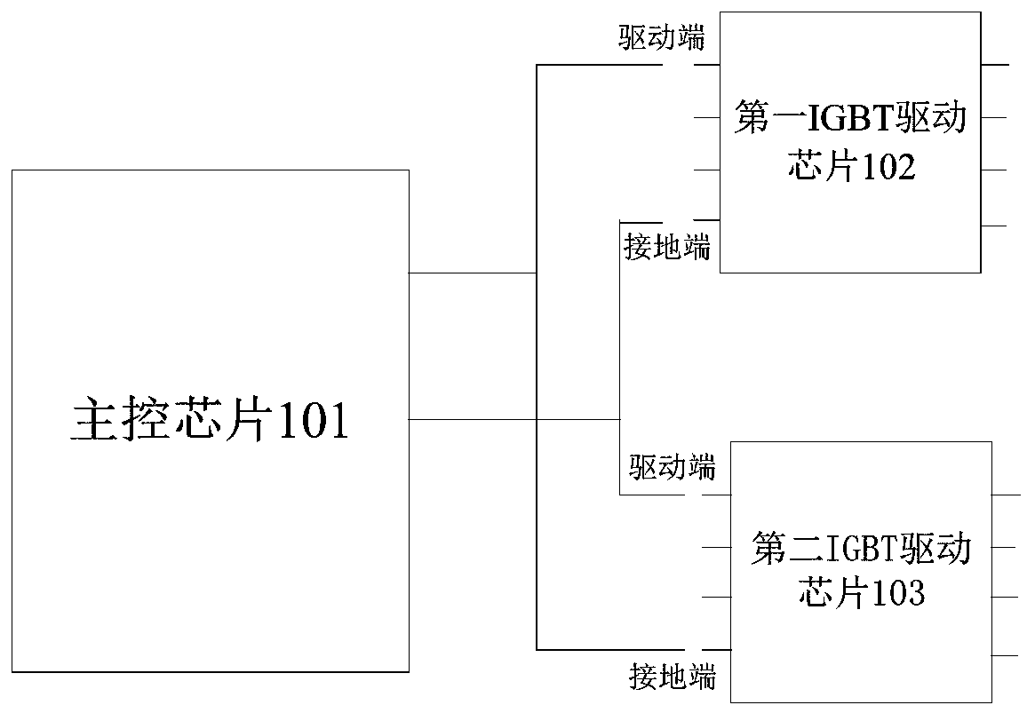
[0040] Aiming at the problem that the upper IGBT and the lower IGBT are turned on at the same time, resulting in a short circuit of the DC bus. In this example, an interlock drive circuit is provided to prevent the DC bus from short-circuiting when the gate drive signals of the upper and lower IGBTs of the same phase are turned on at the same time.

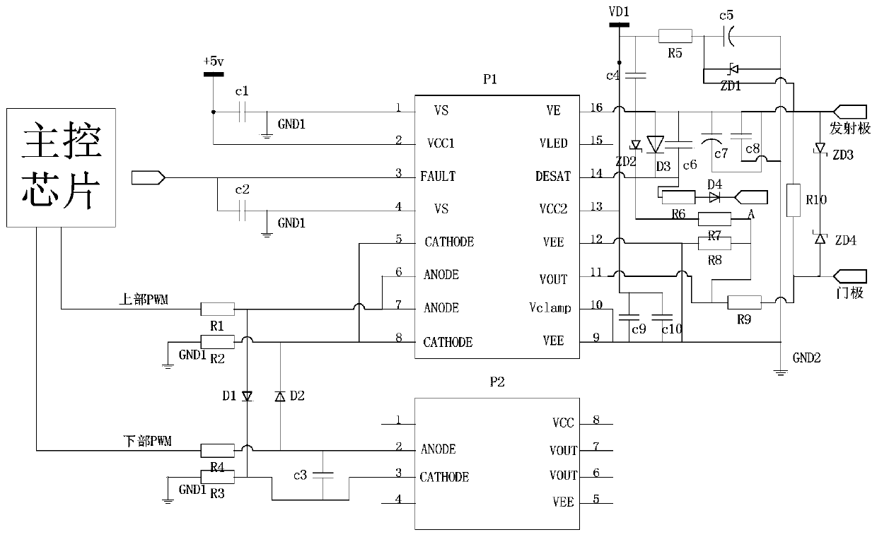
[0041] Specifically, an interlock drive circuit is provided, such as figure 1 As shown, it can include:

[0042] Main control chip 101;

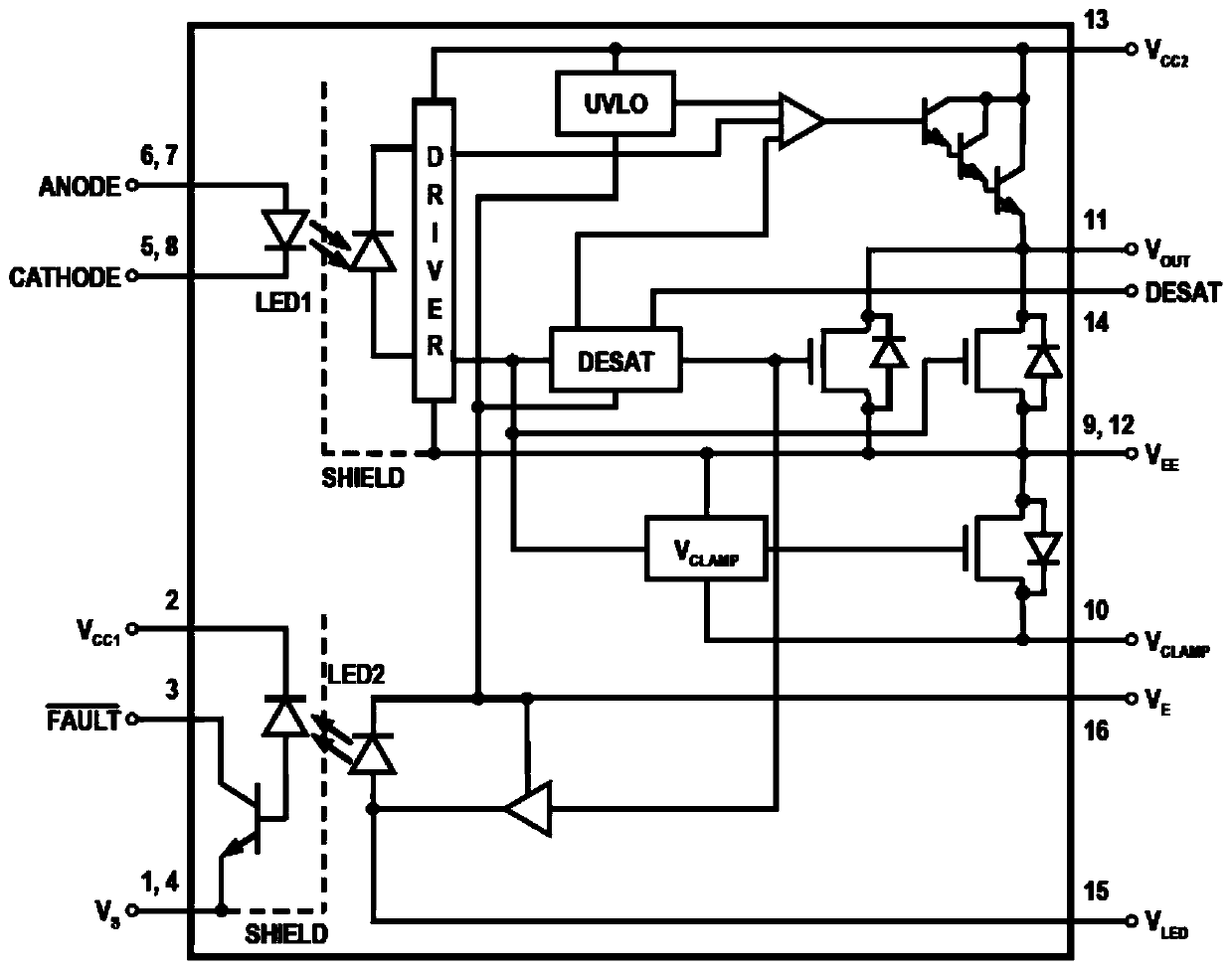
[0043] The first IGBT driving chip 102 is connected to the main control chip, and is configured to ...


PUM


Abstract

The invention provides an interlocking drive circuit. The interlocking drive circuit comprises a main control chip; a first IGBT driving chip which is connected with the main control chip and is usedfor receiving and responding to a driving signal of the main control chip; a second IGBT driving chip which is connected with the main control chip and is used for receiving and responding to the driving signal of the main control chip, wherein a driving signal of the first IGBT driving chip is used as a grounding signal of the second IGBT driving chip; a driving signal of the second IGBT drivingchip is used as a grounding signal of the first IGBT driving chip, and the first IGBT driving chip and the second IGBT driving chip are optical coupling type driving chips. According to the scheme, the simultaneous conduction of the first IGBT driving chip and the second IGBT driving chip can be avoided, the problem of short circuit of the DC bus is avoided, and the technical effect of effectivelyprotecting the driving chips is achieved.

Description

Technical field [0001] The present invention relates to the technical field of drive control, and in particular to an interlocking drive circuit. Background technique [0002] The current IGBT (Insulated Gate Bipolar Transistor, insulated gate bipolar transistor) is mostly driven by a driver chip, or a driver chip is used to drive an IPM (Intelligent Power Module) module. In most motor drive examples, there will be a parasitic turn-on problem caused by Miller capacitors, especially in the 0-15V gate drive, this problem is particularly obvious, this is mainly because the IGBT is turned off. Will produce a high voltage transient, this voltage transient will cause parasitic conduction. [0003] Further, some interference or faults sometimes occur in the circuit to cause PWM output failure or false PWM signals, causing the upper and lower PWM drive chips to simultaneously drive the upper and lower IGBTs of the same phase to be turned on at the same time, thereby causing a short circui...

Claims


Application Information

Patent Timeline
IPC IPC(8): H02M1/092
CPCH02M1/092
Inventor 伍玉行林浩贤陈国明杨帆龙首江宋政璋
Owner GREE ELECTRIC APPLIANCES INC
Why Eureka
Try Eureka