
Impedance matching structure and radio frequency device

A technology of impedance matching and radio frequency devices, which is applied in the field of wireless communication, can solve the problems of small working frequency window value, impedance mismatch at high frequency, complex assembly, etc., achieve high working frequency window value, good impedance matching, and reduce signal reflection Effect

Pending Publication Date: 2020-06-12
TP-LINK
View PDF3 Cites 2 Cited by
  • Summary
  • Abstract
  • Description
  • Claims
  • Application Information

AI Technical Summary

Problems solved by technology

[0006] The purpose of the embodiments of the present invention is to provide an impedance matching structure, aiming at solving the problems of the existing coaxial line-microstrip line transition conversion structure with small working frequency window value, serious impedance mismatch at high frequency, complex assembly and high cost technical issues

Method used


Image

  • Impedance matching structure and radio frequency device
  • Impedance matching structure and radio frequency device
  • Impedance matching structure and radio frequency device

Examples


Embodiment Construction

[0036] In order to make the object, technical solution and advantages of the present invention clearer, the present invention will be further described in detail below in conjunction with the accompanying drawings and embodiments. It should be understood that the specific embodiments described here are only used to explain the present invention, not to limit the present invention.

[0037] It should be noted that when a component is referred to as being “fixed on” or “disposed on” another component, it may be directly or indirectly on the other component. When an element is referred to as being "connected to" another element, it can be directly or indirectly connected to the other element. The orientation or positional relationship indicated by the terms "upper", "lower", "left", "right", etc. are based on the orientation or positional relationship shown in the drawings, and are for convenience of description only, rather than indicating or implying the referred device Or ele...


PUM


Abstract

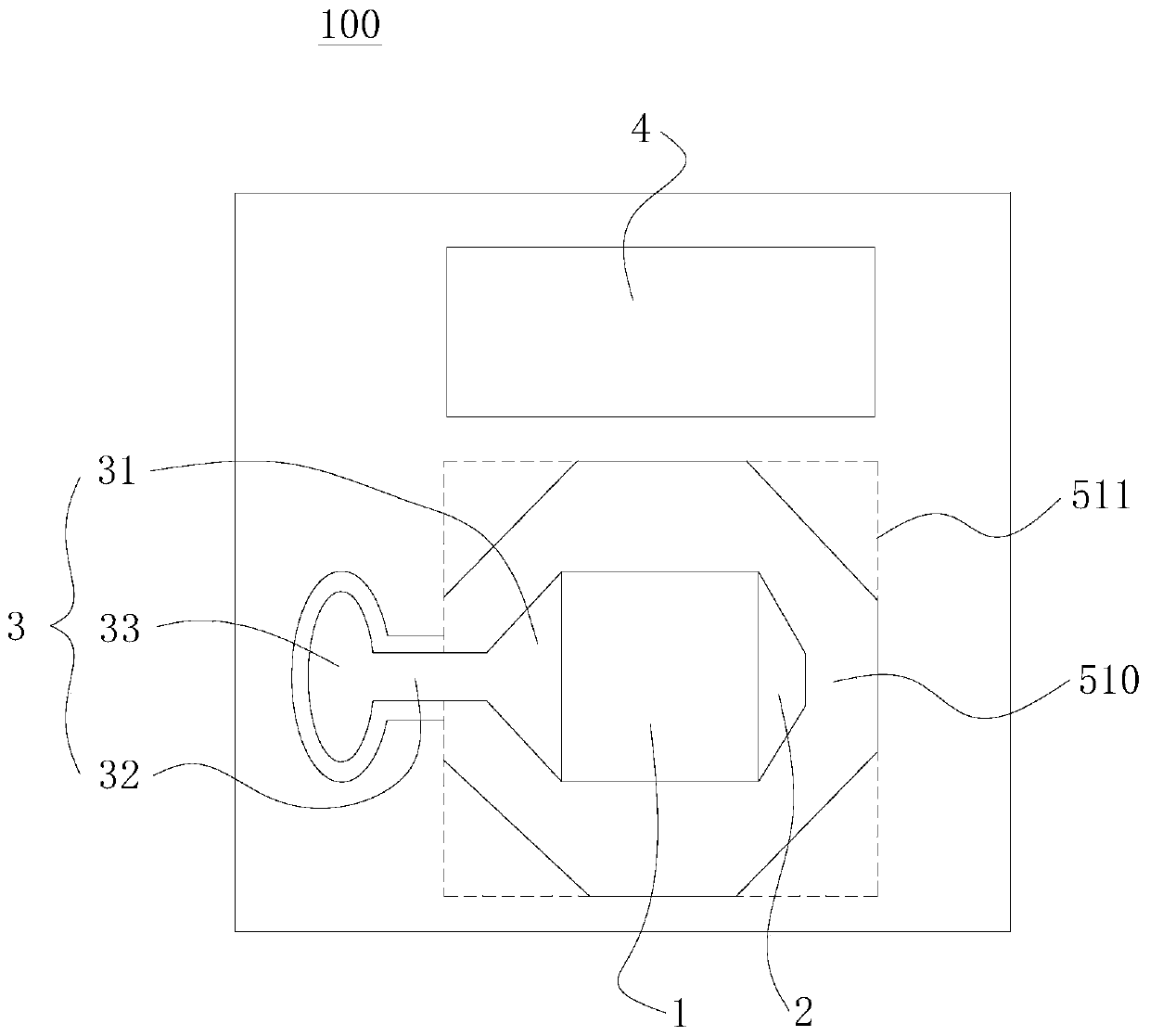
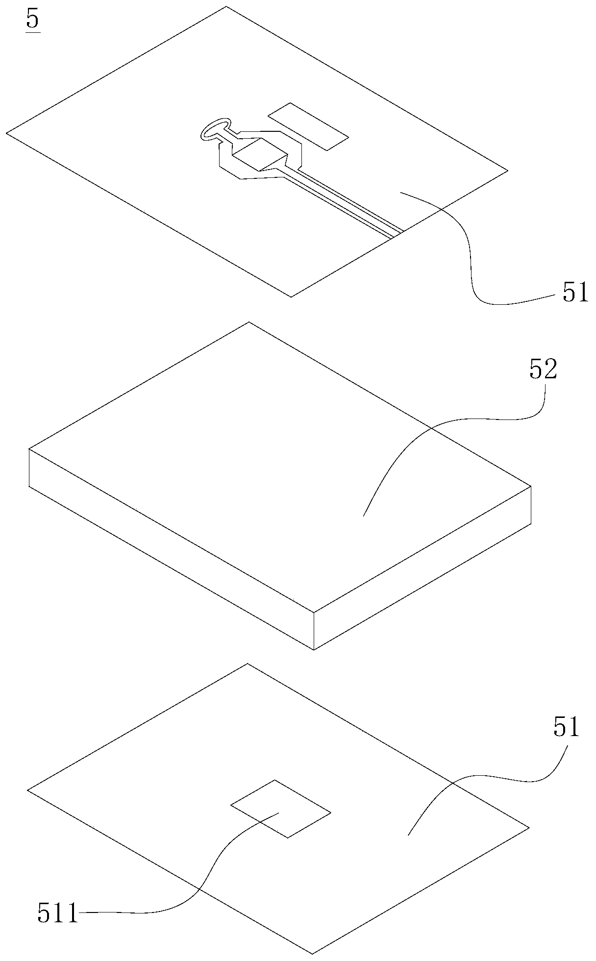
The invention is applicable to the technical field of wireless communication, and provides an impedance matching structure and a radio frequency device, the impedance matching structure is formed on acircuit board with a radio frequency link, and the impedance matching structure comprises a signal bonding pad used for connecting a signal line of a coaxial guided wave structure; the first matchingpart is connected with the signal bonding pad, and the first matching part is in a gradual change shape; the open circuit branch knot comprises a second matching part, and the second matching part isconnected to one end, deviating from the first matching part, of the signal bonding pad and is gradually changed; the at least one grounding bonding pad is used for being connected with a grounding layer of the coaxial guided wave structure; through cooperation of the first matching part and the open circuit branch knot, impedance matching of connection between the coaxial guided wave structure and the radio frequency link is better, signal reflection is reduced, and a working frequency band window value is improved. Moreover, the impedance matching structure is formed on the circuit board, so that the complexity and the cost of manufacturing and assembling can be reduced.

Description

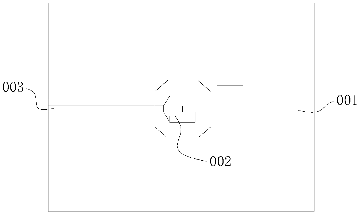
technical field [0001] The invention relates to the technical field of wireless communication, in particular to an impedance matching structure and a radio frequency device. Background technique [0002] For wireless terminal products, the antenna needs to be connected with the microstrip line of the radio frequency link on the PCB (Printed Circuit Board, printed circuit board) through a coaxial cable. Therefore, in order to ensure the normal transmission of radio frequency signals, some conversion structures, such as coaxial pads and coaxial connectors, need to be introduced between the coaxial line and the microstrip line. Common coaxial line-microstrip line transition structures such as figure 1 shown. The inner conductor of the coaxial line 001 is soldered to the signal pad 002 and then connected to the microstrip line 003, and the outer conductor of the coaxial line 001 is soldered to the ground pad. And the coaxial line 001 and the microstrip line 003 are co-located...

Claims


Application Information

Patent Timeline
IPC IPC(8): H04B1/40H04B1/04H04B1/18H01Q1/50
CPCH01Q1/50H04B1/04H04B1/0458H04B1/18H04B1/40
Inventor 史煜仲
Owner TP-LINK
Learn More