Finned pipe bending machine

A technology of pipe bending machine and fins, which is applied in the field of finned pipe bending machines, can solve the problems of difficult production, time-consuming and laborious, and achieve the effects of stable heat exchange performance, firm connection, and improved pipe bending quality.

Inactive Publication Date: 2020-06-16
楼俊鳞
View PDF0 Cites 0 Cited by
  • Summary
  • Abstract
  • Description
  • Claims
  • Application Information

AI Technical Summary

Problems solved by technology

However, every time the R mold is replaced, it is necessary to disassemble, tighten, and readjust the position of the R mold. difficulty

Method used


Image

  • Finned pipe bending machine
  • Finned pipe bending machine
  • Finned pipe bending machine

Examples


Embodiment Construction

[0031] In order to enable those in the technical field to better understand the solutions of the present invention, the technical solutions in the embodiments of the present invention will be clearly and completely described below in conjunction with the drawings in the embodiments of the present invention.

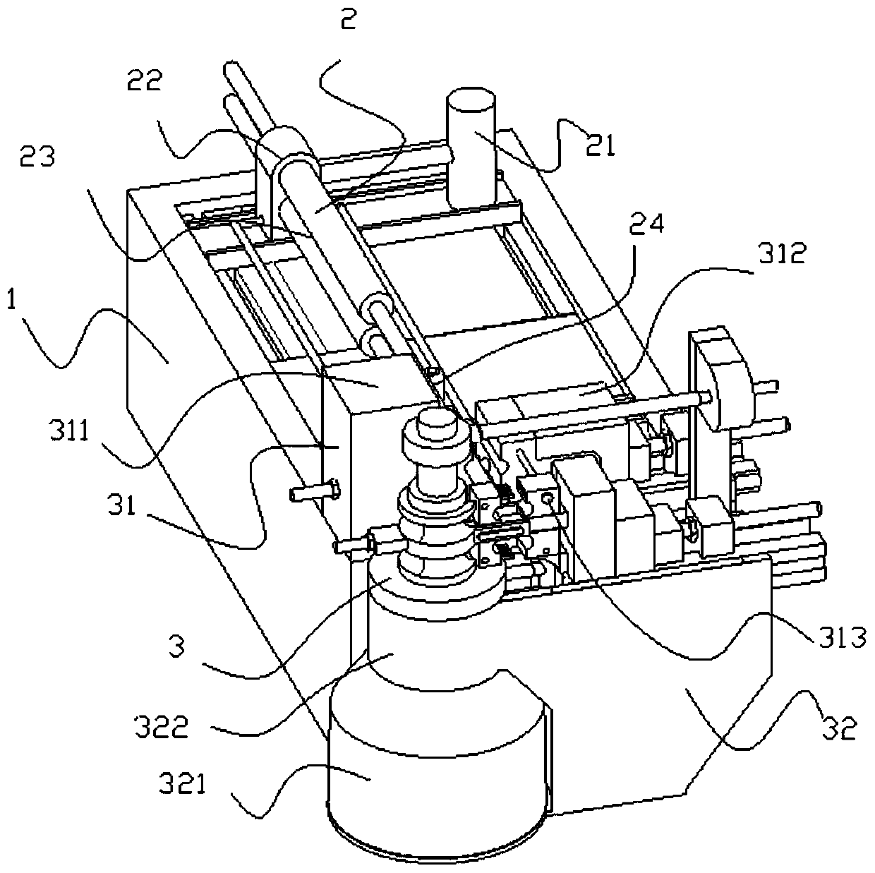
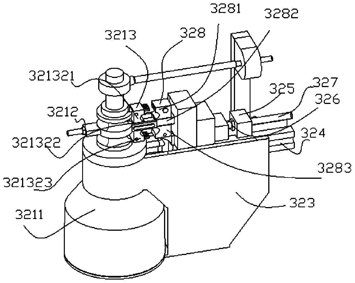
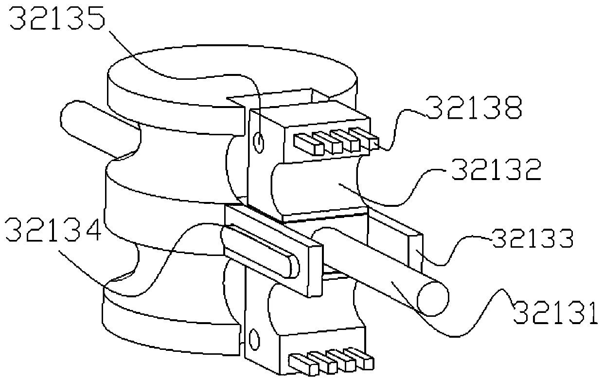
[0032] Such as Figure 1-7 As shown, a finned pipe bending machine includes a machine base 1, a feeding device 2 and a bending device 3; the feeding device 2 is arranged above the machine base; the bending device 3 is arranged in front of the feeding device .

[0033] The feeding device 2 can fix, propel or rotate the pipe, and includes a pneumatic feeder 21, a sliding seat 22, a pipe sleeve 23, and a support member 24; The pneumatic feeder of the sheet pipe bender will not be described in detail; the sliding seat 22 is connected to the pneumatic feeder, and there are multiple through holes in it. Specifically, there are two through holes, and the purpose of setting mult...


PUM


Abstract

The invention discloses a finned pipe bending machine. The machine comprises a machine seat, a feeding device and a bending device; the feeding device can fix, push or rotate pipes; and the bending device is provided with a variable-R mechanism, a deflection mechanism and a rotating piece. According to the machine, the variable-R mechanism is arranged, so that the distance between a screw rod andthe axis of a base is adjusted, any bending radius can be adjusted, and different pipe bending radius requirements can be met; the deflection mechanism is arranged, the self-adaptive force of the pipes cooperates with the inside structure of the deflection mechanism during pipe bending, and deflection in the opposite direction of the rotating direction of the rotating piece is performed, so that pipe surface dents produce during pipe bending are reduced, subsequent bent pipe and fin connection positions are not prone to loosening, and the stability of the performance of a heat exchanger is kept.

Description

technical field [0001] The invention belongs to the technical field of pipe bending, and in particular relates to a finned pipe bending machine. Background technique [0002] In order to improve the heat exchange efficiency of the heat exchanger, it is usually necessary to bend the heat exchange tube into multiple bends, and cover the surface of the heat exchange tube with multiple fins. This requires that when processing finned tubes, the tubes should be bent first. [0003] Existing pipe bending equipment realizes bending by clamping the two ends of the pipe and making one end rotate together with the clamp. During the whole process, the force exerted by the side of the clamp on the pipe is always greater than the force exerted by the inside of the clamp on the pipe, so that the surface of the bent pipe is easy to form dents where it contacts the side of the clamp. When the fins are connected, the larger the connection gap, the connection between the elbow and the fins i...

Claims


Application Information

Patent Timeline
Patent Type & Authority Applications(China)
IPC IPC(8): B21D7/024B21D53/06B21D7/16
CPCB21D7/024B21D7/16B21D53/06
Inventor 楼俊鳞
Owner 楼俊鳞
Why Eureka
Try Eureka