Anti-steel-seepage furnace floor structure

A furnace bottom structure and furnace bottom technology, applied in the direction of manufacturing converters, etc., can solve the problems of steel infiltration, backward movement of working layer bricks, etc., to achieve the effect of high density, avoid triangular packing area, and avoid backward movement

Inactive Publication Date: 2020-06-16
WUGANG REFRACTORY CO LTD
View PDF5 Cites 2 Cited by
  • Summary
  • Abstract
  • Description
  • Claims
  • Application Information

AI Technical Summary

Problems solved by technology

[0003] The purpose of the present invention is to overcome the deficiencies of the prior art, provide a furnace bottom structure of anti-seepage steel, and solve the problem that the working layer bricks in the arc-shaped transition zone of the furnace bottom move backward, resulting in steel seepage

Method used


Image

  • Anti-steel-seepage furnace floor structure
  • Anti-steel-seepage furnace floor structure
  • Anti-steel-seepage furnace floor structure

Examples


Embodiment 1

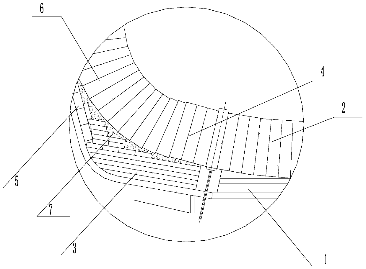
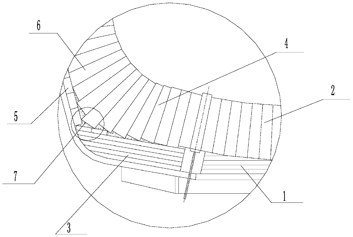
[0016] Such as figure 2 The converter bottom structure of anti-seepage steel shown is composed of furnace bottom area I, furnace bottom arc transition area II, and molten pool transition area III; the furnace bottom area I, furnace bottom arc transition area II, The molten pool transition zone III is equipped with the lower permanent layer lining and the upper working layer lining, which are the permanent layer lining 1 in the furnace bottom area, the working layer lining 2 in the furnace bottom area, the permanent layer lining 3 in the arc-shaped transition area of ​​the furnace bottom, and the furnace lining. The working layer lining 4 in the bottom arc transition area, the permanent layer lining 5 in the molten pool transition area, and the working layer lining 6 in the molten pool transition area; the permanent layer lining 3 in the molten pool transition area; the working layer lining 6 in the molten pool transition area is closely built on the permanent layer lining 5 i...

Embodiment 2

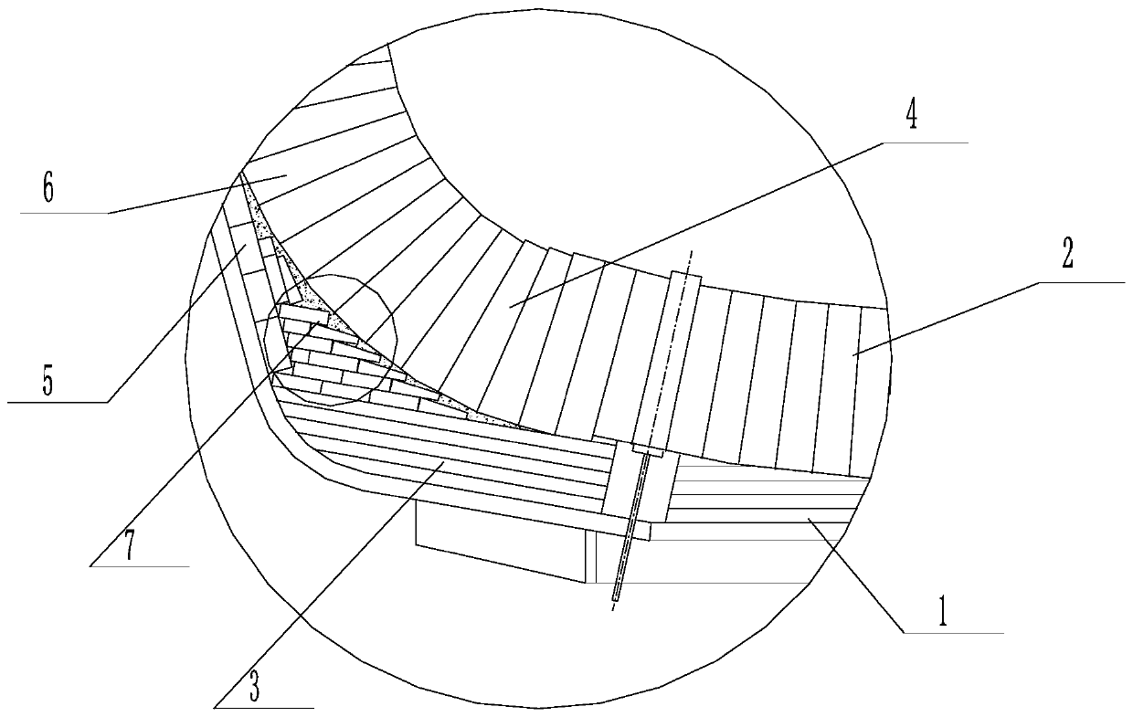
[0019] Such as image 3 The converter bottom structure of anti-seepage steel shown is composed of furnace bottom area I, furnace bottom arc transition area II, and molten pool transition area III; the furnace bottom area I, furnace bottom arc transition area II, The molten pool transition zone III is equipped with the lower permanent layer lining and the upper working layer lining, which are the permanent layer lining 1 in the furnace bottom area, the working layer lining 2 in the furnace bottom area, the permanent layer lining 3 in the arc-shaped transition area of ​​the furnace bottom, and the furnace lining. The working layer lining 4 in the bottom arc transition area, the permanent layer lining 5 in the molten pool transition area, and the working layer lining 6 in the molten pool transition area; the permanent layer lining 3 in the molten pool transition area; the working layer lining 6 in the molten pool transition area is closely built on the permanent layer lining 5 in...


PUM


Abstract

The invention discloses an anti-steel-seepage furnace floor structure. The anti-steel-seepage furnace floor structure is composed of a furnace floor area, a furnace floor arc transition area and a molten pool transition area; the furnace floor area, the furnace floor arc transition area and the molten pool transition area are each provided with a lower permanent layer furnace lining and an upper working layer furnace lining, and the working layer furnace lining of the furnace floor arc transition area is closely built on the permanent layer furnace lining of the furnace floor arc transition area; the working layer furnace lining of the molten pool transition area is closely built on the permanent layer furnace lining of the molten pool transition area; and a triangle area is generated among the permanent layer furnace lining of the furnace floor arc transition area, the working layer furnace lining of the furnace floor arc transition area, the permanent layer furnace lining of the molten pool transition area and the working layer furnace lining of the molten pool transition area. The anti-steel-seepage furnace floor structure can give full play to the advantages of high density andhigh strength of shaping products.

Description

technical field [0001] The invention relates to the technical field of steelmaking equipment, in particular to a furnace bottom structure of anti-seepage steel. Background technique [0002] There are two main types of converter bottoms: flattened bottom and progressive flattened bottom. At present, progressive flattened bottom is widely used at home and abroad. This kind of masonry has good integrity and can effectively decompose heat in the furnace bottom and molten pool area. Stress, prolong the service life of the converter and other advantages. The defect of this structure is that there will be a large number of triangular areas in the permanent layer and the working layer in the arc transition area of ​​the furnace bottom and the molten pool arc transition area, and the triangular area is filled with magnesia or magnesia-chrome fillers Form the packing area. Due to the poor strength of the filling material, the filling material is easy to loosen and break under the c...

Claims


Application Information

Patent Timeline
Patent Type & Authority Applications(China)
IPC IPC(8): C21C5/48C21C5/44
CPCC21C5/44C21C5/48
Inventor 蔡长秀谭喜阳徐源周辉徐志华
Owner WUGANG REFRACTORY CO LTD
Why Eureka
Try Eureka