
Thin film deposition method and device

A thin film deposition and equipment technology, which is applied in the field of thin film deposition methods and equipment, can solve problems such as uneven mixing and uneven thickness distribution of deposited films, and achieve the effects of improving uniformity and controllable particle pollution

Inactive Publication Date: 2020-06-16
BEIJING NAURA MICROELECTRONICS EQUIP CO LTD
View PDF2 Cites 1 Cited by
  • Summary
  • Abstract
  • Description
  • Claims
  • Application Information

AI Technical Summary

Problems solved by technology

Using this kind of buffer chamber and the method of depositing thin films by PEALD above will cause the first precursor and the second precursor to mix unevenly in the buffer chamber, and further, it will form a unilateral phenomenon that the amount of the first precursor is adsorbed on the crystal surface. resulting in uneven distribution of deposited film thickness

Method used


Image

  • Thin film deposition method and device
  • Thin film deposition method and device
  • Thin film deposition method and device

Examples


Embodiment Construction

[0038] In order to enable those skilled in the art to better understand the technical solution of the present invention, the thin film deposition method and equipment provided by the present invention will be described in detail below with reference to the accompanying drawings.

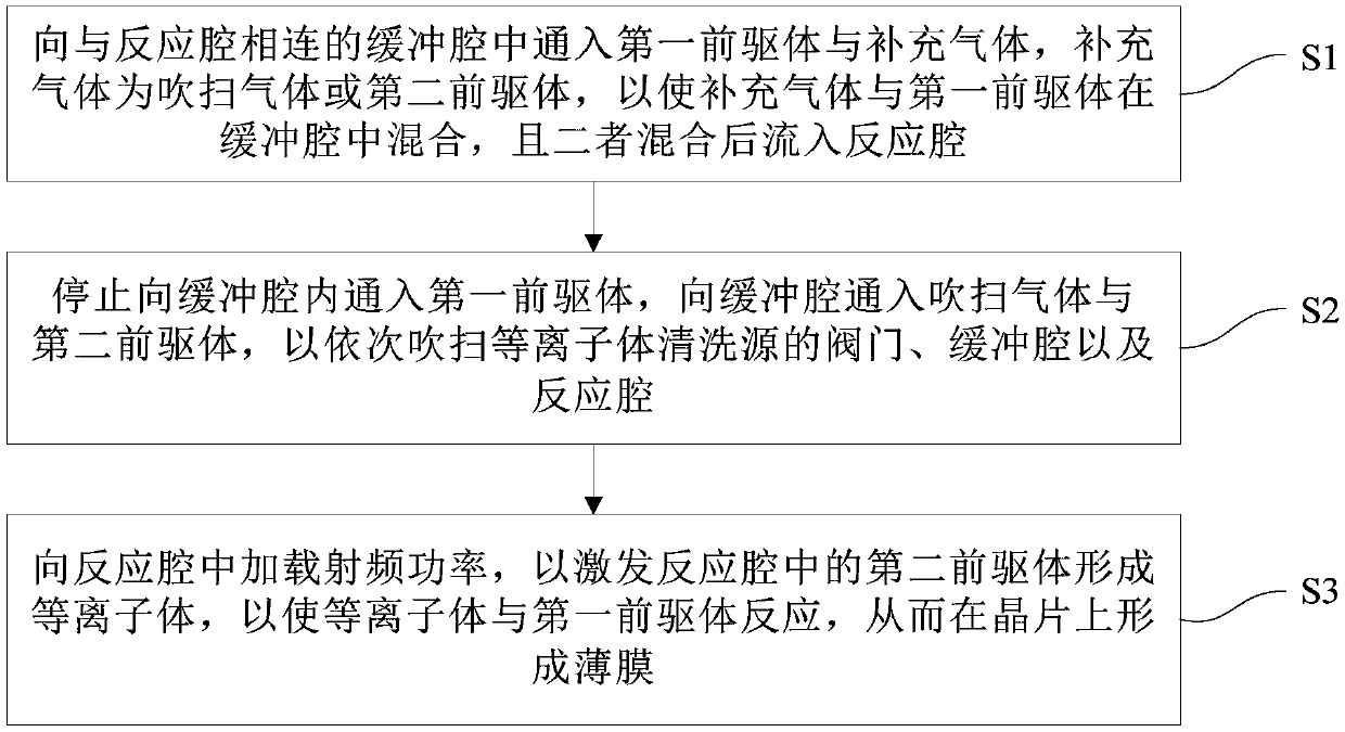
[0039] Such as figure 1 Shown is the first flow chart of the thin film deposition method of the embodiment of the present invention, including the following steps:

[0040] Step S1: Introduce the first precursor and supplementary gas into the buffer chamber connected to the reaction chamber, the supplementary gas is purge gas or the second precursor, so that the supplementary gas and the first precursor are mixed in the buffer chamber, and The two are mixed and flow into the reaction chamber.

[0041] In the embodiment of the present invention, the purge gas is the gas used to purge the valve of the plasma cleaning source, and the second precursor is a substance that does not react with the first pr...


PUM


Abstract

The invention provides a t thin film deposition method and device. The method comprises the following steps that S1, a first precursor and makeup gas are led into a buffer cavity connected with a reaction cavity, the makeup gas is blowing gas or a second precursor, the makeup gas is mixed with the first precursor in a buffer cavity, and after mixing of the makeup gas and the first precursor, a mixture flows into a reaction cavity; S2, leading of the first precursor into the buffer cavity is stopped, the blowing gas and the second precursor are led into the buffer cavity, a valve of a plasma cleaning source, the buffer cavity and the reaction cavity are blown in sequence; and S3, radio frequency power is loaded in the reaction cavity, the second precursor in the reaction cavity is stimulated to form plasmas, the plasmas react with the first precursor, and a thin film is formed on a wafer. Through the method and device, the distribution uniformity of deposited thin film thickness can beimproved.

Description

technical field [0001] The invention relates to the field of semiconductor manufacturing, in particular to a thin film deposition method and equipment. Background technique [0002] Plasma Enhanced Atomic Layer Deposition (Plasma Enhanced Atomic Layer Deposition, hereinafter referred to as PEALD), the method of depositing thin films by PEALD generally includes the following four steps: [0003] Step 1: After the first precursor, the second precursor and the valve purge gas of the plasma cleaning source are mixed in the buffer chamber, they enter the reaction chamber, and the first precursor is adsorbed on the wafer in the reaction chamber. [0004] Step 2: stop the input of the first precursor, and continue to pass the second precursor and valve purge gas into the reaction chamber to purge the unadsorbed first precursor in the reaction chamber. [0005] Step 3: Turn on the radio frequency device, so that the plasma plasma generated in the reaction chamber excites the molecu...

Claims


Application Information

Patent Timeline
IPC IPC(8): C23C16/455C23C16/505
CPCC23C16/4408C23C16/455C23C16/505
Inventor 秦海丰史小平兰云峰王勇飞纪红赵雷超张文强
Owner BEIJING NAURA MICROELECTRONICS EQUIP CO LTD
Learn More