
Multi-cutter disc large-section vertical shaft tunneling device

A large-section, multi-cutter technology, used in shaft equipment, well sinking, mining equipment, etc., can solve problems such as equipment shortage and backward construction methods.

Active Publication Date: 2020-06-16
CHINA RAILWAY ENGINEERING EQUIPMENT GROUP CO LTD
View PDF5 Cites 1 Cited by
  • Summary
  • Abstract
  • Description
  • Claims
  • Application Information

AI Technical Summary

Problems solved by technology

[0003] Aiming at the technical problems of current large-section shaft construction methods and equipment shortages, the present invention proposes a multi-cutter large-section shaft tunneling device

Method used


Image

  • Multi-cutter disc large-section vertical shaft tunneling device
  • Multi-cutter disc large-section vertical shaft tunneling device
  • Multi-cutter disc large-section vertical shaft tunneling device

Examples


Embodiment 1

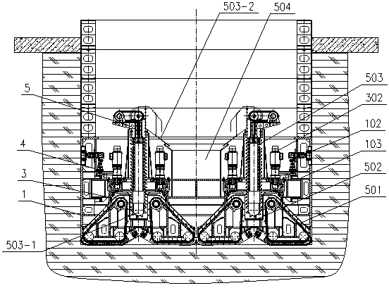
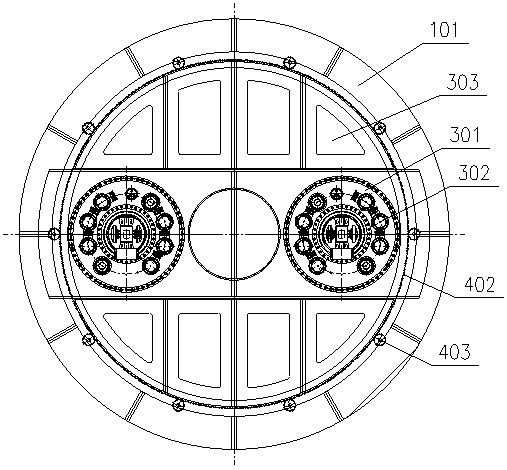
[0022] Embodiment 1: as figure 1 As shown, a multi-cutter large-section shaft excavation device includes a shield body 1. The shield body 1 is composed of several shield body block units 101 fixedly connected. An excavation device is arranged under the shield body 1. The shield body 1 A rotating track 103 is arranged on the top, and the small-circle turning device 3 is movably arranged on the turning track 103. The small-circle turning device 3 is connected with the large-circle turning drive device 4 and the excavation device respectively, and the large-circle turning drive device 4 is connected with the shield body 1. Fixed connection; the shield body 1 is provided with a main machine slag discharge device 5, which is a mechanical slag discharge device, and the main machine slag discharge device 5 is connected with the excavation device and the small circle slewing device 3 respectively.

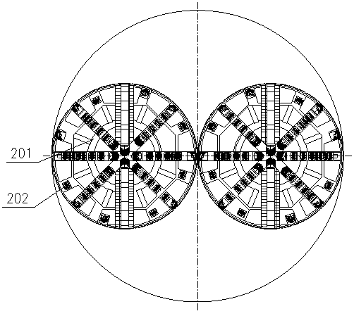
[0023] Such as image 3 As shown, the excavation device includes several cutterheads ...

Embodiment 2

[0029] Embodiment 2: Multi-cutter large-section vertical shaft excavation device, when the main machine slag discharging device 5 is a fluid slagging device, the mud pumping device in the fluid slagging mode is used to collect the first stage of the main machine slagging device 5 The slag device 501, the primary slag collection cylinder 502, the vertical lifting device 503 and the secondary slag collection cylinder 504 are removed, the mud pump is installed, the mud water pipeline is connected, the cutter head is excavated in the mud water, and the principle of mud water pumping is used. The mud carries the dregs out of the well, and through the separation of mud and water, the separation of the dregs and the circulation of the mud are completed.

[0030] All the other structures are the same as in Example 1.

Embodiment 3

[0031] Embodiment 3: Multi-cutter large-section shaft excavation device, when the main machine slag discharging device 5 adopts a fluid slagging device, the vacuum pumping device in the fluid slagging mode is used to collect the first-stage slag in the main machine slagging device 5 The device 501, the primary slag collection cylinder 502, the vertical lifting device 503 and the secondary slag collection cylinder 504 are removed, a vacuum pump is installed, and relevant pipelines are connected. The slag is transported to the outside of the well to complete the slag discharge operation.

[0032] All the other structures are the same as in Example 1.


PUM


Abstract

The invention provides a multi-cutter disc large-section vertical shaft tunneling device. The multi-cutter disc large-section vertical shaft tunneling device comprises a shield body. An excavation device is arranged below the shield body. A rotating track is arranged on the shield body. A small circumferential rotating device is movably arranged on the rotating track and is respectively connectedwith a large circumferential rotating driving device and an excavating device. The large circumferential rotating driving device is fixedly connected with the shield body. The shield body is internally provided with a main machine slag discharging device. The main machine slag discharging device is correspondingly connected with the excavating device and the small circumferential rotating device.According to the multi-cutter disc large-section vertical shaft tunneling device, a large section is excavated through revolution and rotation of a plurality of cutters, muck generated in the large section is collected through the main machine slag discharging device, full-section muck collecting and overall mechanized operation are achieved, automatic and integrated parallel construction operation of excavation and slag discharging is achieved, equipment is convenient to disassemble and assemble, the number of operators is reduced, the labor intensity of personnel is reduced, and the safety and construction efficiency of vertical shaft construction are greatly improved.

Description

technical field [0001] The invention relates to the technical field of shaft excavation, in particular to a multi-cutter large-section shaft excavation device. Background technique [0002] At present, shafts are generally excavated artificially or semi-mechanized, or conventional drilling equipment is used for construction. The two methods meet the construction needs of most shaft projects to a certain extent. With the development of the depth direction, the disadvantages of manual semi-mechanized excavation methods in terms of safety and efficiency have become more and more prominent, seriously affecting the progress of the project; while conventional drilling equipment is mainly suitable for shaft construction with medium or small sections, and cannot be directly used for large Cross-section shaft engineering, and a large amount of muck generated during the excavation of large-section shafts, it is necessary to remove the dregs generated during the excavation process in a...

Claims


Application Information

Patent Timeline
Patent Type & Authority Applications(China)
IPC IPC(8): E21D1/06E21D1/03
CPCE21D1/03E21D1/06
Inventor 郑康泰贺飞肖威吕旦赵飞杨聚辉周倩肖晶娜徐光亿付玉龙张恒桑梓叶志娟鲁超
Owner CHINA RAILWAY ENGINEERING EQUIPMENT GROUP CO LTD
Learn More