Supercharge Your Innovation With Domain-Expert AI Agents!

Device and method for obtaining purification efficiency of high radioactive gas purification equipment

A technology for radioactive gas and purification equipment, which is applied to measurement devices, testing of mechanical components, and testing of machine/structural components, etc., can solve problems such as reduced purification performance, threats to the surrounding environment and personnel safety, and untimely replacement of purification equipment. Achieve the effect of ensuring and personnel safety and ensuring safe and stable operation

Active Publication Date: 2020-06-16
THE 404 COMPANY LIMITED CHINA NAT NUCLEAR
View PDF5 Cites 0 Cited by
  • Summary
  • Abstract
  • Description
  • Claims
  • Application Information

AI Technical Summary

Problems solved by technology

However, the purification performance of the purification equipment will gradually decrease after long-term operation in the radioactive and acidic process environment, which will affect the gas purification effect and easily cause the abnormal increase in the radioactive level of the effluent carried by the external exhaust, which seriously threatens the surrounding environment and personnel safety.
[0004] Usually, the purification equipment of the process exhaust system in the radioactive plant has no efficiency detection means or methods during operation, and the operating performance of the purification equipment can only be judged indirectly through the differential pressure measuring instrument and the fixed gamma dose rate measuring instrument, and its purification cannot be accurately known. Efficiency, which easily leads to untimely replacement of purification equipment, resulting in an abnormal increase in the radioactive level of the effluent carried by the external exhaust

Method used


Image

  • Device and method for obtaining purification efficiency of high radioactive gas purification equipment

Examples


Embodiment Construction

[0066] The present invention will be described in further detail below in conjunction with the accompanying drawings and specific embodiments.

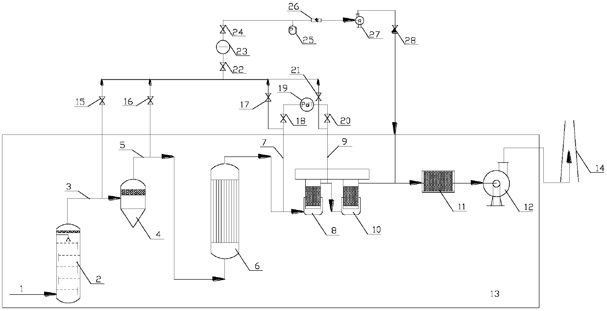
[0067] Such as figure 1 A device for obtaining the purification efficiency of strong radioactive gas purification equipment is shown, including a manual stop valve, a sampling box (23), a pressure gauge (25), a flow meter (26), a vacuum pump (27), and a check valve (28) .

[0068] The strong radioactive gas process exhaust system is composed of multiple strong radioactive gas purification equipment connected, specifically including the elution tower (2), trap (4), and gas cooler (6) connected in sequence inside the equipment room (13) , medium-efficiency filter (8), high-efficiency filter A (10), high-efficiency filter B (11), blower fan (12), and the chimney (14) that is positioned at the outside of equipment room. In parallel with the medium-efficiency filter (8), a differential pressure gauge (19) is provided, and the front pipel...


PUM

PropertyMeasurementUnit
Diameteraaaaaaaaaa

Abstract

The invention relates to the technical field of radioactive gas purification, and particularly discloses a device and a method for obtaining purification efficiency of high radioactive gas purification equipment. The device comprises a manual stop valve, a sampling box, a pressure gauge, a flow meter, a vacuum pump and a check valve, wherein the sampling box, the pressure gauge, the flow meter, the vacuum pump and the check valve are connected in sequence. The method comprises the following steps: 1, placing filter paper A; 2, sampling radioactivity concentration activity of a gas at an inletof a catcher; 3, placing filter paper B; 4, sampling the radioactivity concentration activity of the gas at an outlet of the catcher; 5, placing filter paper C; 6, sampling the radioactivity concentration activity of the gas at the inlet of a medium-efficiency filter; 7, placing filter paper D; 8, sampling the radioactivity concentration activity of the gas at the outlet of the medium-efficiency filter; and 9, processing data. According to the device and the method, the purification efficiency of the purification equipment can be rapidly and accurately obtained, and a reliable basis is provided for judging a purification capacity of the purification equipment.

Description

technical field [0001] The invention belongs to the technical field of radioactive gas purification, and in particular relates to a device and method for obtaining purification efficiency of strong radioactive gas purification equipment. Background technique [0002] During the production process of the radioactive process plant, a large amount of process exhaust with high radioactivity is generated, and the process exhaust must undergo multi-stage purification treatment to be qualified before being discharged to the natural environment. Because the process exhaust is highly radioactive and corrosive, and contains complex components such as fragmentation products and organic compounds, and has high humidity, the comprehensive performance requirements for purification equipment are very high. [0003] Commonly used radioactive process exhaust purification equipment mainly includes leaching towers, traps, coolers, medium-efficiency filters, high-efficiency filters, etc. All pu...

Claims


Application Information

Patent Timeline
IPC IPC(8): G01M99/00G01M13/00
CPCG01M13/00G01M99/005
Inventor 王镇李飞颜官超刘程远李跃斌
Owner THE 404 COMPANY LIMITED CHINA NAT NUCLEAR
Features
  • R&D
  • Intellectual Property
  • Life Sciences
  • Materials
  • Tech Scout
  • Unparalleled Data Quality
  • Higher Quality Content
  • 60% Fewer Hallucinations
Learn More