
Chip thrust testing method

A test method and thrust technology, applied in the field of chip thrust test, can solve the problems of low detection efficiency, high cost, and large difference in detection results, and achieve the effects of improving detection accuracy, improving detection efficiency, and precise positioning

Pending Publication Date: 2020-06-16
佛山市诺普材料科技有限公司
View PDF0 Cites 0 Cited by
  • Summary
  • Abstract
  • Description
  • Claims
  • Application Information

AI Technical Summary

Problems solved by technology

[0004] However, in practice, the thrust test equipment in the prior art judges the initial position of the thimble on the chip (that is, the point of force application) through human visual observation and feeling, and the method of judging only by visual observation and feeling cannot guarantee the force of the thimble. The initial position (force application point) of each different chip is the same, that is, accurate positioning cannot be achieved. Because the contact position between the thimble and the chip is different (that is, the force application point of the thimble is different), the torque that the chip can withstand is different. The results vary greatly, and the difference in test results often leads to the inclusion of qualified products in defective products, or the inclusion of defective products in qualified products, which affects the quality of electronic products, and the detection efficiency is low and the cost is high.

Method used


Image

  • Chip thrust testing method
  • Chip thrust testing method
  • Chip thrust testing method

Examples


Embodiment Construction

[0027] Below, the present invention will be further described in conjunction with the accompanying drawings and specific implementation methods. It should be noted that, under the premise of not conflicting, the various embodiments described below or the technical features can be combined arbitrarily to form new embodiments. .

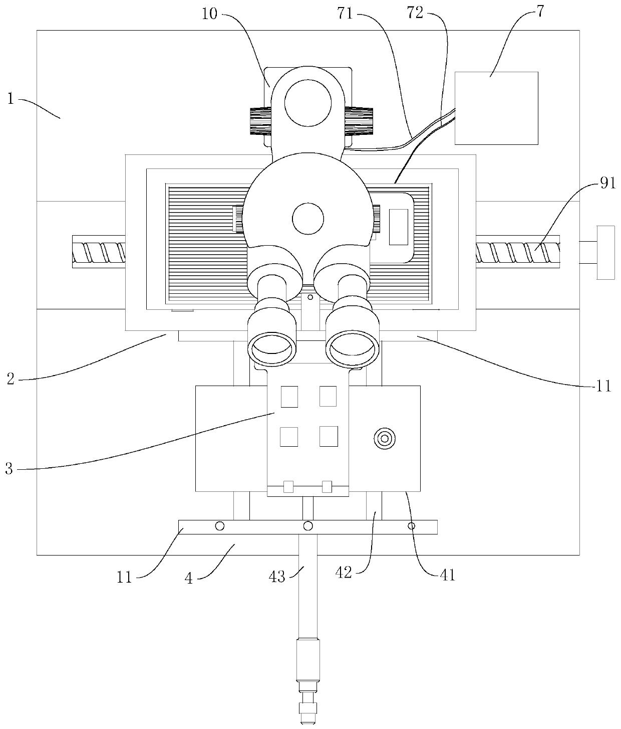
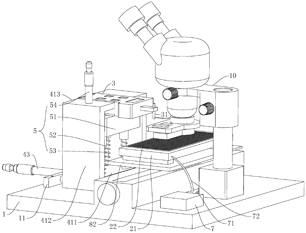
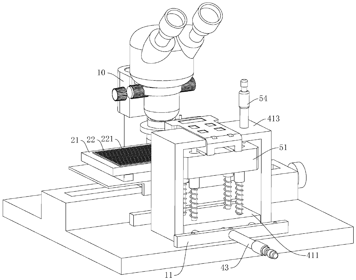
[0028] see Figure 1-Figure 4, shows a chip thrust testing device in a preferred embodiment of the present invention, the chip thrust testing equipment includes a base 1, and a fixture 2 installed on the base 1, a thrust tester 3, a first X-direction horizontal The moving drive mechanism 4, the Z-direction lifting drive mechanism 5, the indicating device 7, the second X-direction traversing drive mechanism, the Y-direction traversing drive mechanism and the microscope 10, the clamp 2 is used to clamp the bracket with the chip bonded, the first The X-direction lateral movement drive mechanism 4 is used to drive the thrust tester 3 to move in a directio...


PUM


Abstract

The invention discloses a chip thrust testing method, which adopts chip thrust testing equipment for carrying out thrust testing on a chip. The chip thrust testing equipment comprises a base, and a clamp, a thrust tester, a first X-direction transverse movement driving mechanism, a Z-direction lifting driving mechanism and an indicating device which are installed on the base. The chip thrust testing method comprises a starting point position determining step and a force application point determining step. The starting point position determination step is implemented by enabling the thrust tester to get close to a bracket positioned on the clamp until an ejector pin on the thrust tester is in contact with the top surface of the bracket so as to lighten an indicating lamp, and taking the position of the ejector pin as a starting point position at the moment. The force application point determination step is implemented by taking the starting point position as a reference point, driving the thrust tester to move upwards for a set displacement, and enabling the thrust tester to get close to the side part of the chip until the ejector pin is in contact with the side part of the chip, and taking the position of the ejector pin as the position of a force application point. The chip thrust testing method can realize precise positioning, and can improve the detection efficiency while improving the detection precision, so that the cost is reduced.

Description

technical field [0001] The invention relates to the technical field of chip thrust testing, in particular to a chip thrust testing method. Background technique [0002] With the continuous development and improvement of the semiconductor industry, more and more electronic components are integrated into a semiconductor material. Therefore, the volume of many electronic products is getting smaller and smaller, and the role they can play is also getting bigger and bigger. [0003] As one of the essential and important components in electronic products, the quality of the chip directly affects the overall quality of the electronic product. The bonding is firm and avoids affecting the performance of electronic products. At present, the thrust test of the chip is generally carried out by thrust test equipment. During the test, the bracket bonded with the chip is fixed on the fixture, and then the thimble of the thrust tester is directly moved to the side of the chip and offset a...

Claims


Application Information

Patent Timeline
Patent Type & Authority Applications(China)
IPC IPC(8): G01N19/04G01M13/00G01B7/00G01B11/00
CPCG01B7/003G01B11/00G01M13/00G01N19/04
Inventor 彭涛丁勇
Owner 佛山市诺普材料科技有限公司
Features
  • Generate Ideas
  • Intellectual Property
  • Life Sciences
  • Materials
  • Tech Scout
  • Unparalleled Data Quality
  • Higher Quality Content
  • 60% Fewer Hallucinations
Learn More