High-speed modulator based on annular reflector

A ring-shaped mirror and modulator technology, applied in instruments, nonlinear optics, optics, etc., can solve the problems of narrow bandwidth, large loss, and large size of the modulator, reducing size, reducing insertion loss, and increasing bandwidth. Effect

Active Publication Date: 2020-06-16
UNITED MICROELECTRONICS CENT CO LTD
View PDF26 Cites 0 Cited by
  • Summary
  • Abstract
  • Description
  • Claims
  • Application Information

AI Technical Summary

Problems solved by technology

[0004] Aiming at the deficiencies in the prior art, the present invention provides a high-speed modulator based on a ring mirror, which is used to solve the shortcomings of the existing modulators, such as large size, narrow bandwidth, and large loss

Method used


Image

  • High-speed modulator based on annular reflector
  • High-speed modulator based on annular reflector

Examples


Embodiment Construction

[0013] The present invention will be described in further detail below in combination with the accompanying drawings, and specific implementation methods will be given.

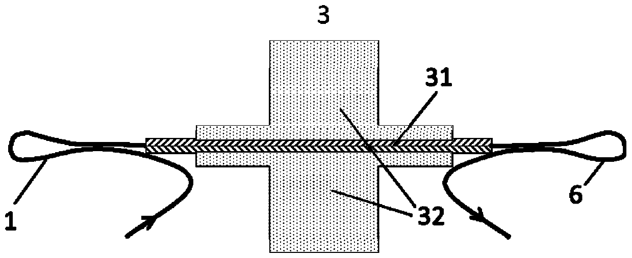
[0014] refer to Figure 1-Figure 2 , according to an embodiment of the present invention, a high-speed modulator based on a ring mirror, including an input ring mirror 1, a modulation arm 3 and an output ring mirror 6 connected in sequence, the input ring mirror 1 and the output ring mirror 6 at both ends of the modulation arm 3 A resonant cavity is formed between the output ring mirrors 6 to enhance the energy density of the light field.

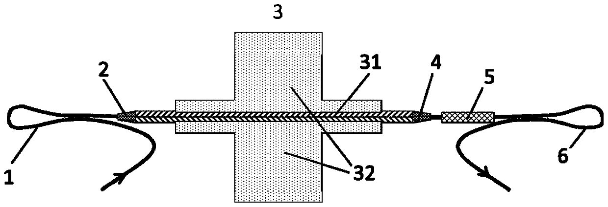
[0015] According to another embodiment of the present invention, the modulator further includes an input speckle converter 2 and an output speckle converter 4, and the input speckle converter 2 is arranged between the input annular mirror 1 and the modulation arm 3 ; The output speckle converter 4 is arranged between the modulation arm 3 and the output ring mirror 6 . Th...


PUM


Abstract

The invention provides a high-speed modulator based on an annular reflector. The high-speed modulator comprises an input annular reflector, a modulation arm and an output annular reflector which are connected in sequence, wherein a resonant cavity is formed between the input annular reflector and the output annular reflector at the two ends of the modulation arm to enhance the light field energy density. The high-speed modulator has the advantages of being small in size, large in working bandwidth range, small in loss, simple in structure, easy to manufacture and suitable for large-scale manufacturing and commercial application.

Description

technical field [0001] The invention relates to a light modulation device, in particular to a high-speed modulator based on a ring reflector. Background technique [0002] The silicon optical modulator can realize high-speed data modulation and is one of the core devices of the high-speed silicon optical chip. In order to achieve high-speed transmission, the structure of traveling wave electrodes is usually used. The existing modulator structure has limitations in the dielectric constant and size of the manufacturing material, resulting in a large gap between the microwave group refractive index of the traveling wave electrode and the light wave group refractive index, so there is a large speed mismatch between the light wave and the microwave transmission. It will reduce the modulation bandwidth, and it is difficult to match the characteristic impedance to 50 ohms; at the same time, most modulator structures use silicon as the substrate, and there is still a large microwave...

Claims


Application Information

Patent Timeline
Patent Type & Authority Applications(China)
IPC IPC(8): G02F1/00G02F1/015G02F1/025G02F1/19
CPCG02F1/009G02F1/015G02F1/025G02F1/19Y02D30/70
Inventor 胡志朋邵斯竹肖志雄吴月朱兴国冯俊波郭进
Owner UNITED MICROELECTRONICS CENT CO LTD
Why Eureka
Try Eureka