
Switchable antennas for wireless applications

a wireless application and switchable technology, applied in the field of integrated antenna arrays, can solve problems such as intermittent reception, reduced data speed, and system vulnerability, and achieve the effects of broad operating wavelength range, enhanced antenna pattern, and small footprin

Active Publication Date: 2017-01-10
COMMSKY TECH CORP
View PDF6 Cites 3 Cited by
  • Summary
  • Abstract
  • Description
  • Claims
  • Application Information

AI Technical Summary

Benefits of technology

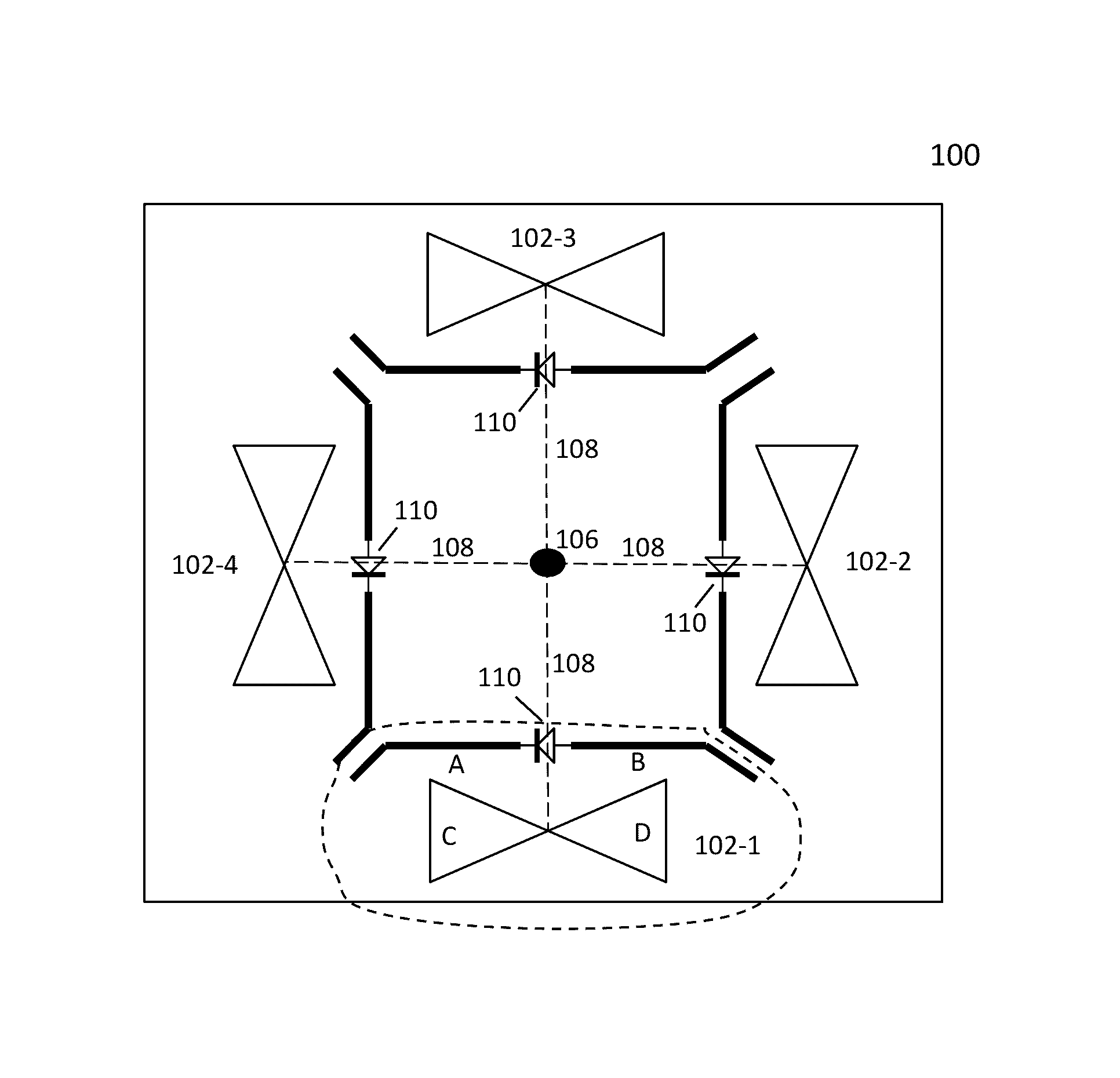
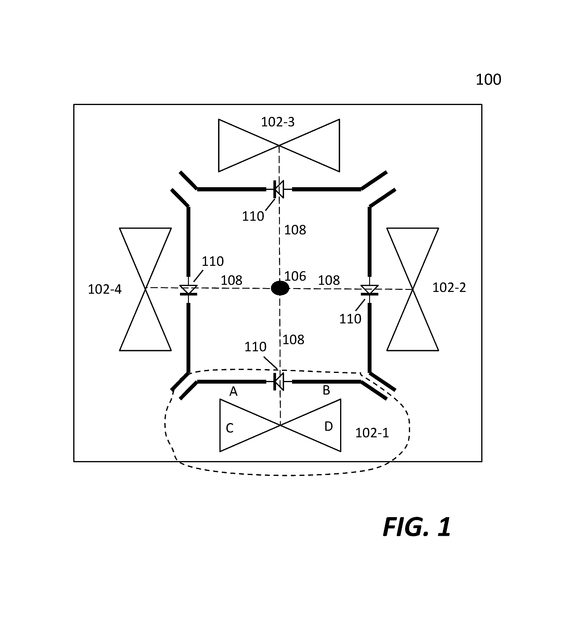
[0013]One of the objects, features and advantages of the present invention is to provide a smart antenna that is amenable to small footprint, broad operating wavelength range, enhanced antenna pattern, lower cost, and easier manufacturing process. Other objects, features, benefits and advantages, together with the foregoing, are attained in the exercise of the invention in the following description and resulting in the embodiment illustrated in the accompanying drawings.

Problems solved by technology

Such systems are vulnerable to problems caused by multipath effects.
The late arrival of scattered portions of the signal causes problems such as fading, cut-out (cliff effect), and intermittent reception (picket fencing).
In a digital communications system like the Internet, it can cause a reduction in data speed and an increase in the number of errors.
Most of the smart antennas in use today have some undesired nulls in the antenna patterns.
If not carefully planned, nulls can unintentionally prevent reception of a signal and fail to transmit a signal.

Method used


Image

  • Switchable antennas for wireless applications
  • Switchable antennas for wireless applications
  • Switchable antennas for wireless applications

Examples


Embodiment Construction

[0023]The detailed description of the invention is presented largely in terms of procedures, steps, logic blocks, processing, and other symbolic representations that directly or indirectly resemble the operations of communication devices coupled to networks. These process descriptions and representations are typically used by those skilled in the art to most effectively convey the substance of their work to others skilled in the art.

[0024]Reference herein to “one embodiment” or “an embodiment” means that a particular feature, structure, or characteristic described in connection with the embodiment can be included in at least one embodiment of the invention. The appearances of the phrase “in one embodiment” in various places in the specification are not necessarily all referring to the same embodiment, nor are separate or alternative embodiments mutually exclusive of other embodiments. Further, the order of blocks in process flowcharts or diagrams representing one or more embodiments...


PUM


Abstract

Techniques of designing an antenna array with antenna units controlled electronically are described. Through controlling the combination of the reflectors in each of the antenna units, a desired antenna pattern is formed, adapting to the environment, and providing reliable and efficient links between two transceivers. According to one aspect of the present invention, a switch (e.g., a diode) is used to couple two reflectors. The diode is controlled to be on or off so that the reflectors are conductively integrated or separated.

Description

CROSS-REFERENCE TO RELATED APPLICATION[0001]This is a continuation-in-part of co-pending U.S. application Ser. No. 13 / 872,078, entitled “Multi-channel multi-sector smart antenna system”, filed Apr. 27, 2013.BACKGROUND OF THE INVENTION[0002]Field of Invention[0003]The invention generally is related to the area of antennas, and more particularly related to integrated antenna arrays structured in a way and controlled electronically to form a desired antenna pattern adapting to an environment, and providing reliable and efficient links between two transceivers.[0004]Related Art[0005]An antenna system is an indispensable component in communication systems. In conventional wireless communications, a single antenna is used at the source, and another single antenna is used at the destination. This is called SISO (single input, single output). Such systems are vulnerable to problems caused by multipath effects. When an electromagnetic field (EM field) is met with obstructions such as hills, ...

Claims


Application Information

Patent Timeline
Patent Type & Authority Patents(United States)
IPC IPC(8): H01Q3/24H01Q19/30H01Q21/20H01Q19/10H01Q1/38H01Q21/24
CPCH01Q3/24H01Q1/38H01Q19/108H01Q19/30H01Q21/20H01Q21/24
Inventor CHENG, PO-SHINLI, XINWANG, DANIELSHEN, JUNZHAO, GEORGE
Owner COMMSKY TECH CORP
Learn More