Hypersonic flight test device boosting section control system simulation platform
A simulation platform and hypersonic technology, applied in general control systems, control/regulation systems, instruments, etc., to achieve the effect of improving development efficiency
- Summary
- Abstract
- Description
- Claims
- Application Information
AI Technical Summary
Problems solved by technology
Method used
Image
Examples
Embodiment 1
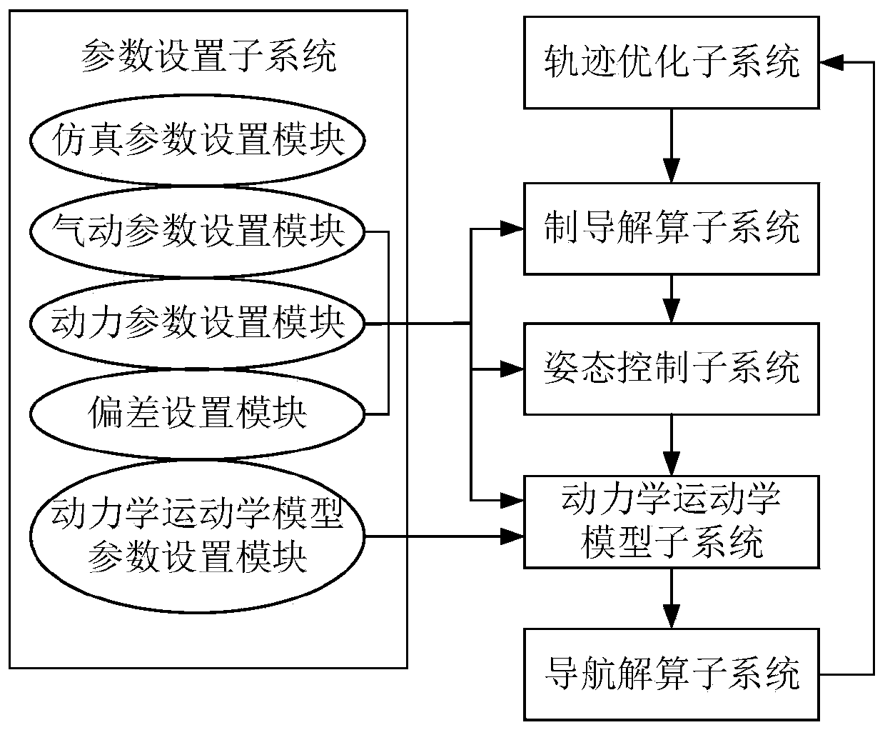
[0040] Embodiment 1 of the present invention provides a simulation platform for the control system of the booster section of a hypersonic flight test vehicle. The simulation platform includes a parameter setting subsystem, a trajectory optimization subsystem, a guidance solution calculation subsystem, an attitude control subsystem, and a dynamic Kinematics model subsystem and navigation solution subsystem.
[0041] It should be noted that the simulation model of the hypersonic test vehicle is a combination of the upper stage and the lower stage of the booster rocket.
[0042] The parameter setting subsystem includes a simulation parameter setting module, a dynamics kinematics parameter setting module, a dynamic parameter setting module, a pneumatic setting module and a deviation setting module. The simulation parameter setting module is system initialization setting, the dynamic parameter setting module, aerodynamic setting module and deviation setting module are connected wit...
Embodiment 2
[0055] Embodiment 2 of the present invention provides a kind of simulation method of hypersonic speed vehicle booster section control system, and simulation platform adopts this simulation method in embodiment 1, specifically comprises the following steps:
[0056] S1: The trajectory optimization subsystem provides a flight trajectory for the guidance solution subsystem through trajectory optimization;
[0057] S2: The parameter setting subsystem provides data for the guidance solution subsystem, the control subsystem and the dynamic kinematics model subsystem;
[0058] S3: The guidance calculation subsystem is used to calculate the outer loop slow loop rudder control amount according to the flight trajectory and parameter data, and transmit it to the attitude control system;
[0059] S4: The attitude control system inputs the outer-loop slow-loop rudder control amount of the guidance solution subsystem and the inner-loop fast-loop control amount calculated by itself according...
Embodiment 3
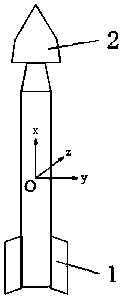
[0064] Embodiment 3 of the present invention provides a kind of assembly motion simulation model, and the simulation model applicable to the simulation platform described in Embodiment 1 is an assembly; the assembly includes an upper level 2 and a lower level 1; and the upper level 2 is a face Said, the following level 1 is axisymmetric.
[0065] The simulation model is as follows:
[0066] (1) Define the relevant coordinate system
[0067] Body coordinate system ox b the y b z b : The origin is the center of mass of the assembly, the x-axis points to the head of the assembly, that is, the test vehicle, the y-axis is perpendicular to the symmetry plane of the test vehicle and the x-axis, and the z-axis is determined according to the right-hand rule.
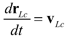
[0068] launch coordinate system ox L the y L z L : The origin is at the launch point, the x-axis points to the launch direction, the y-axis is perpendicular to the horizontal plane, and the z-axis is determined by the righ...
PUM
 Abstract
Description
Claims
Application Information
 - R&D Engineer
- R&D Manager
- IP Professional
- Industry Leading Data Capabilities
- Powerful AI technology
- Patent DNA Extraction
Browse by: Latest US Patents, China's latest patents, Technical Efficacy Thesaurus, Application Domain, Technology Topic.
© 2024 PatSnap. All rights reserved.Legal|Privacy policy|Modern Slavery Act Transparency Statement|Sitemap


