Temperature control sprinkler

A sprinkler and water pipe technology, applied in watering devices, gardening, botany equipment and methods, etc., can solve the problems of increasing people's labor, reducing enzyme activity, affecting plant growth, etc. effect of labor

Active Publication Date: 2020-06-19
威海仁昌电子有限公司
View PDF10 Cites 2 Cited by
  • Summary
  • Abstract
  • Description
  • Claims
  • Application Information

AI Technical Summary

Problems solved by technology

[0002] At present, in some small breeding bases, plants need to be watered in a timely manner, especially at high temperatures, because the plants are at high temperatures, which enhances the transpiration of the plants, causing the plants to lose too much water, and The activity of enzymes in plants is reduced, which affects

Method used


Image

  • Temperature control sprinkler
  • Temperature control sprinkler
  • Temperature control sprinkler

Examples


Embodiment 1

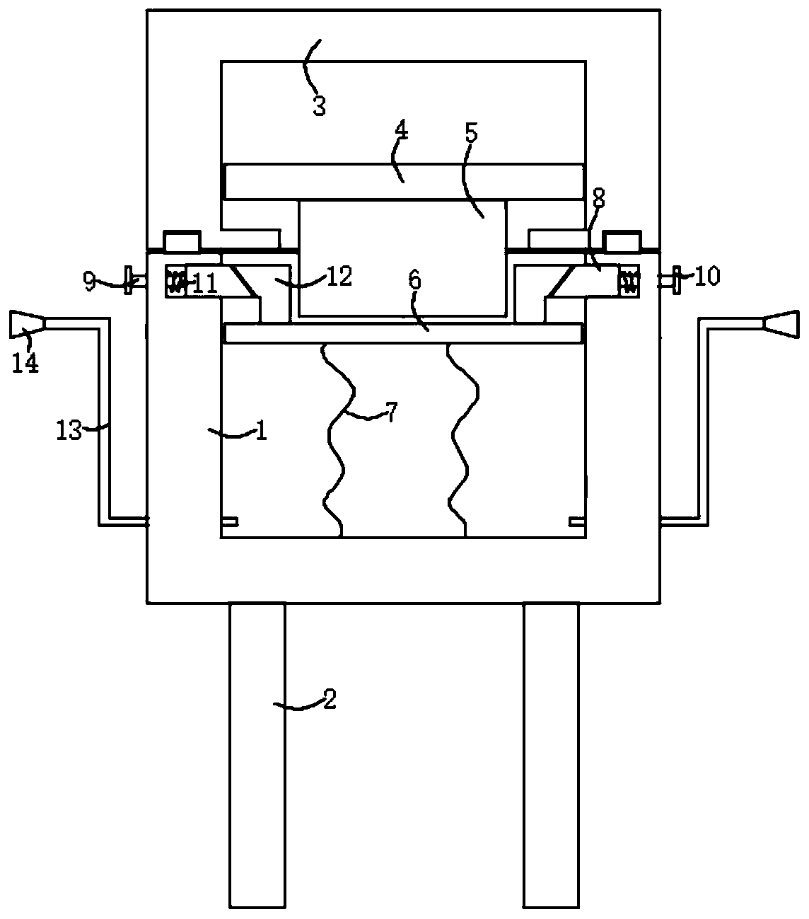
[0018] refer to figure 1 , a temperature-controlled sprinkler, comprising a base 1, a plurality of support rods 2 fixedly connected to the bottom of the base 1, a transparent top frame 3 threadedly connected to the base 1, and a first piston plate slidably connected to the inner side wall of the transparent top frame 3 4. The bottom of the first piston plate 4 is fixedly connected with a pressure block 5;

[0019] It should be noted that: the top of the base 1 is fixedly connected with a threaded ring, and the bottom of the transparent top frame 3 is provided with an annular threaded groove corresponding to the threaded ring, wherein the transparent top frame 3 is set to be transparent, which is convenient for people to see the first internal piston. The position of the plate 4, so as to judge whether to add water again.

[0020] Wherein, the base 1 is provided with a second piston plate 6, and the bottom of the second piston plate 6 is connected with the inner bottom of the ...

Embodiment 2

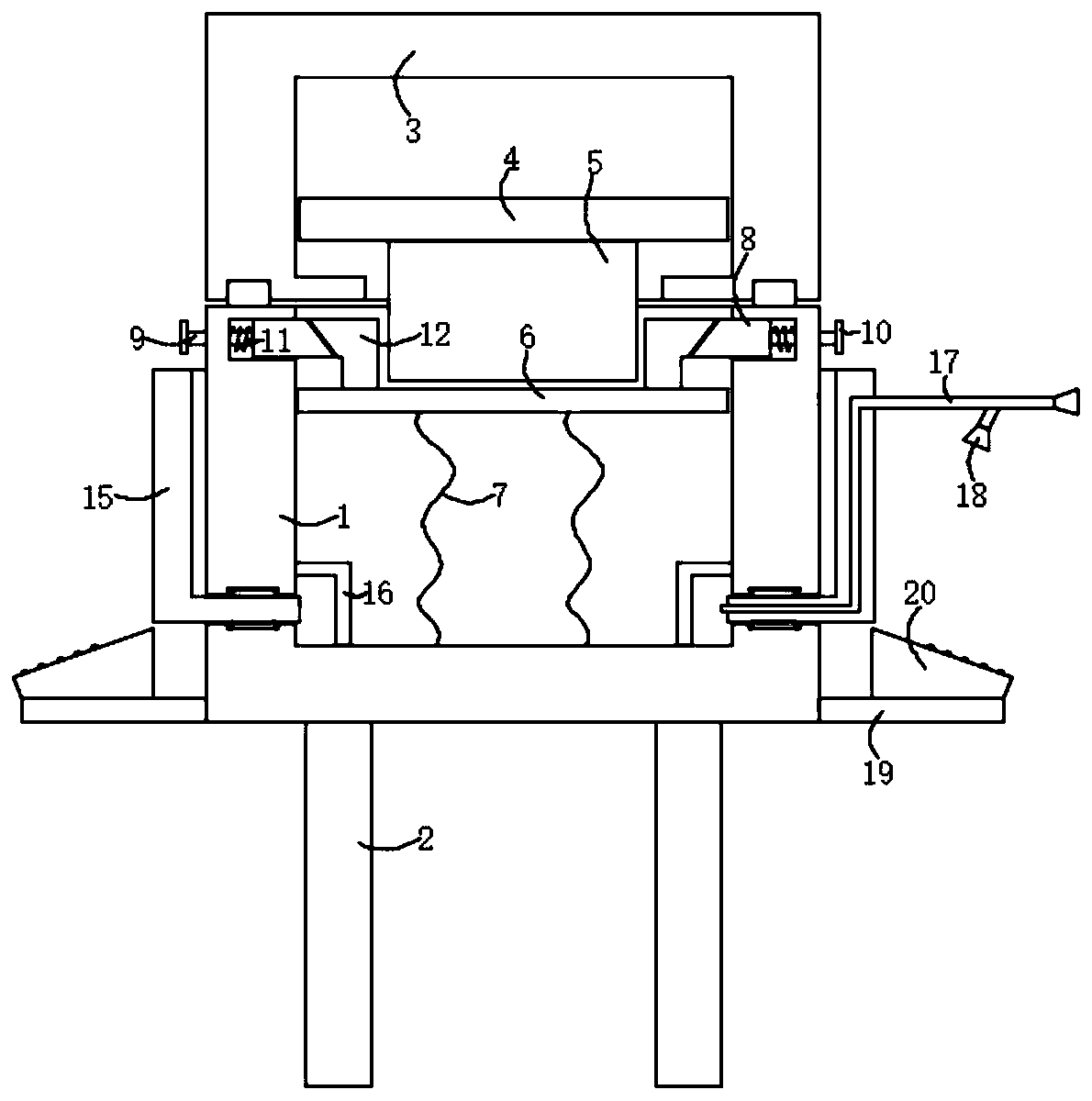
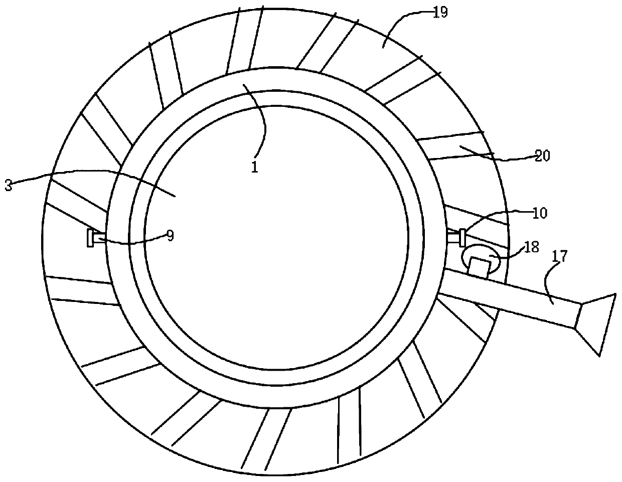
[0027] refer to Figure 2-3 The difference between this embodiment and Embodiment 1 is that the sprinkling mechanism includes a ring-shaped connection frame 15, the base 1 is provided with a rotating groove corresponding to the connection frame 15, and the inner wall of the base 1 is fixedly connected with a plurality of L-shaped fixed The rod 16 is fixedly connected with a plurality of second water pipes 17 in the connection frame 15, the second water pipe 17 is fixedly connected with a second nozzle at one end away from the connection frame 15, and the bottom of the second water pipe 17 is fixedly connected with a third nozzle 18 arranged obliquely , the outer side wall of the base 1 is fixedly sleeved with a mounting ring 19, and the top of the mounting ring 19 is fixedly connected with an obliquely arranged stopper 20, so that when the second piston plate 6 moves downward, the bottom of the second piston plate 6 will The water body sprays out from the second nozzle and the...


PUM


Abstract

The invention discloses a temperature control sprinkler. The temperature control sprinkler comprises a base, wherein a plurality of supporting rods are fixedly connected to the bottom of the base, a transparent top frame is in threaded connection to the base, and a first piston plate is slidably connected to the inner side wall of the transparent top frame. According to the temperature control sprinkler, a second piston plate is lifted upwards, then a water body is poured into the base, and then the second piston plate is slightly put down, so that the stability of the second piston plate is guaranteed through the action of an abutting block and a wedge block; and the transparent top frame is in threaded connection to the base, so that the air pressure in the first piston plate and the transparent top frame is continuously increased at a high temperature, the first piston plate is pushed to move downwards, the abutting block is separated from the wedge block, then the second piston plate moves downwards under the action of a first spring, then the water body below the second piston plate is extruded, and the extruded water body can be sprayed out through a sprinkling mechanism, andas a result, the labor of operators is reduced to a great extent, and the process of automatically sensing the high temperature and automatically watering is realized.

Description

technical field [0001] The invention relates to the technical field of sprinkler devices, in particular to a temperature-controlled sprinkler. Background technique [0002] At present, in some small breeding bases, plants need to be watered in a timely manner, especially at high temperatures, because the plants are at high temperatures, which enhances the transpiration of the plants, causing the plants to lose too much water, and The activity of enzymes in plants is reduced, which affects the growth and metabolism of plants, which will affect the growth of plants. Therefore, people need to water and cool plants, which increases people's labor, and it is difficult to control the temperature of the air. Promptly watering too much is also unfavorable for the growth of plant, brings puzzlement for people's cultivation like this. Contents of the invention [0003] The object of the present invention is to propose a temperature-controlled sprinkler in order to solve the problem...

Claims


Application Information

Patent Timeline
IPC IPC(8): A01G25/02A01G25/16
CPCA01G25/02A01G25/16
Inventor 丁水生
Owner 威海仁昌电子有限公司
Why Eureka
Try Eureka