Suction assembly for endoscope and endoscope

An endoscope and component technology, applied in the field of endoscope, can solve the problems of unreliable rebound, large force, poor pressing feel, etc., and achieve the effects of reliable function, simple structure and improved reliability.

Pending Publication Date: 2020-06-19
重庆金山医疗技术研究院有限公司
View PDF12 Cites 4 Cited by
  • Summary
  • Abstract
  • Description
  • Claims
  • Application Information

AI Technical Summary

Problems solved by technology

[0004] The first purpose of the present invention is to provide an endoscope suction button for the disadvantages of poor pressing feel, unreliable rebound or excessive force of mechanical buttons in the existing technology of suction components for endoscopes. Through electromagnetic control, the suction effect is better; through the button switch to control the suction state, the pressing feel is better

Method used


Image

  • Suction assembly for endoscope and endoscope
  • Suction assembly for endoscope and endoscope
  • Suction assembly for endoscope and endoscope

Examples


Embodiment 1

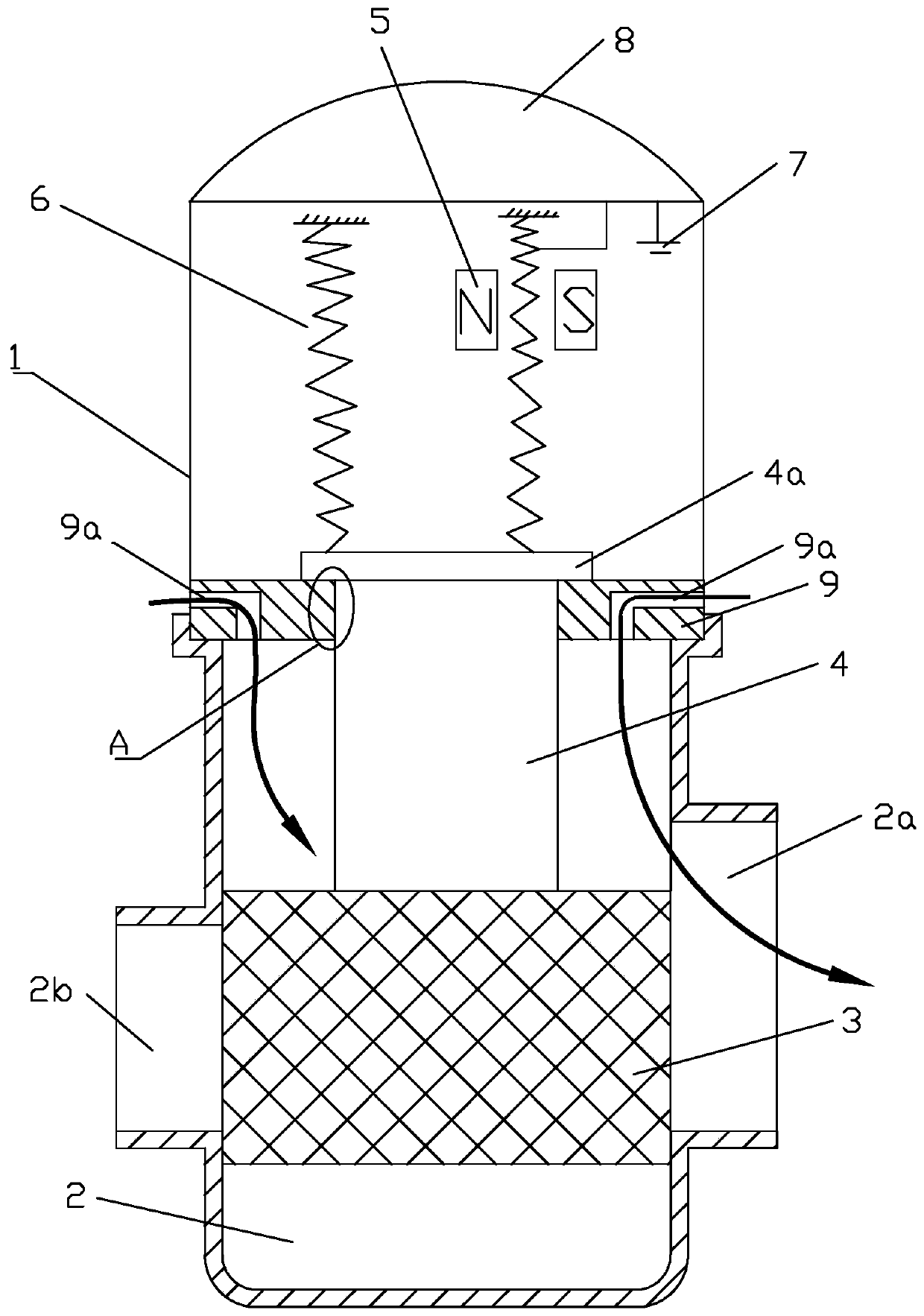
[0023] Example 1, see figure 1 , figure 2 , a suction assembly for an endoscope, including a button assembly 1 and a suction cavity 2, the suction cavity 2 is provided with a negative pressure port 2a and a suction port 2b; the button assembly 1 includes a valve core reset by a spring 6, The valve core slidably cooperates with the suction cavity 2 to connect or block the negative pressure port 2a and the suction port 2b; the button assembly 1 also includes a housing, and a valve stem 4 is arranged inside the housing, and the front end of the valve stem 4 is fixed A seal 3 is connected, and the seal 3 is located inside the suction cavity 2, and the seal 3 and the valve stem 4 constitute the valve core; the tail end of the valve stem 4 is connected with the spring 6, and a DC electromagnet assembly 5 is also arranged in the housing , the DC electromagnet assembly 5 forms a magnetic coupling with the valve stem 4; the DC electromagnet assembly 5 and the spring 6 are respectivel...

Embodiment 2

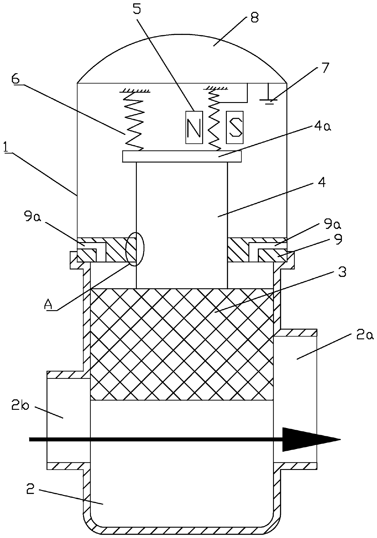
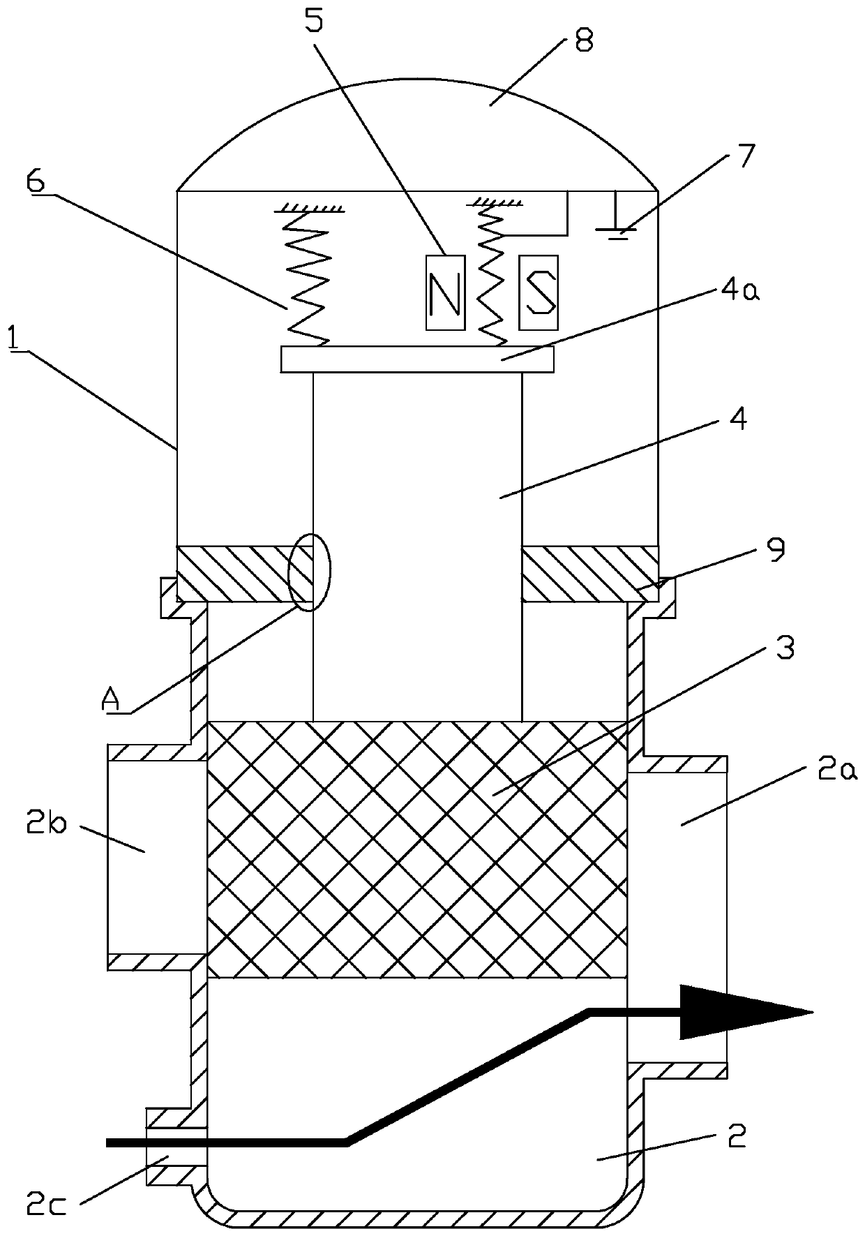
[0026] Example 2, see image 3 , Figure 4 , the spring 6 is a tension spring; the DC electromagnet assembly 5 drives the valve core to move in the direction of pulling the spring 6 after being energized. The suction cavity 2 is in an inverted convex shape, and the bottom or lower part of the cavity inside the suction cavity 2 protrudes downward. The air intake channel 2c communicates with the external atmosphere to replace the intake air provided on the stopper 9. aisle. Wherein, the negative pressure port 2a and the suction port 2b are arranged on the upper part of the suction cavity 2 .

[0027] The rest of the structure of this embodiment is the same as that of Embodiment 1, and will not be repeated here.

Embodiment 3

[0028] Example 3, combined with Figure 1~4 , an endoscope, comprising the suction assembly of embodiment 1 or 2.


PUM


Abstract

The invention discloses a suction assembly for endoscope and an endoscope. The suction assembly comprises a button assembly and a suction cavity, and a negative pressure connector and a suction connector are arranged on the suction cavity; the button assembly comprises a valve element reset through a spring, and the valve element is in sliding fit with the suction cavity so that the negative pressure connector and the suction connector can be connected or disconnected. The button assembly further comprises a shell, a valve rod and a sealing piece are arranged in the shell, and the valve rod and the sealing piece form a valve element. The tail end of the valve rod is connected with a spring, and a direct-current electromagnet assembly forming magnetic coupling with the valve rod is furtherarranged in the shell. The direct-current electromagnet assembly and the spring are used for driving the valve element to move in the opposite directions. And the upper end of the shell is provided with a key switch assembly for connecting the direct-current electromagnet assembly with a direct-current power supply. Endoscope comprises said suction assembly. The beneficial effects are that the suction assembly is simple in structure, convenient to operate, reliable in function, good in pressing hand feeling and multiple in selectable structural forms; endoscope has the same effect as previously described.

Description

technical field [0001] The invention relates to an endoscope control part, in particular to an endoscope suction component and an endoscope with the button. Background technique [0002] The suction button on the operating part of the endoscope is mainly used to control the suction function of the head end, to realize the switching of suction or non-suction of liquid, debris or gas in the patient's body. In the natural state, the gas in the air flows to the suction pump through the hole of the suction button. When the suction button is pressed, the channel inside the suction button and the outer space of the mirror body is isolated, and the channel between the suction pump and the head end is opened to achieve the suction effect , which can be used to remove fluid, debris or gas from a patient. [0003] In the prior art, most of the suction buttons are mechanical, and the return of the suction valve core is realized by a spring, and the pressing feel is not good; in additio...

Claims


Application Information

Patent Timeline
Patent Type & Authority Applications(China)
IPC IPC(8): A61B1/015A61B1/00
CPCA61B1/015A61B1/00137
Inventor 王聪邓安鹏
Owner 重庆金山医疗技术研究院有限公司
Why Eureka
Try Eureka